The line shown as BK extends to the tell and is known as the "hot side" of the electrical system It provides a circuit
to the door switch and ulumately to all electrically operated components that dashed lines enclose the timer, cycle selector, and door switches
through the timer switches You will note This is to indicate that these switches are
inside the component structure
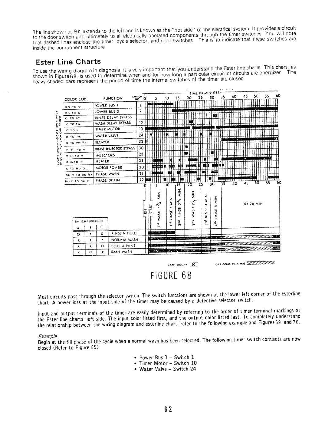
Ester Line Charts
To use the wiring diagram in diagnosis, i_ is very important that you understand the Ester tine charts This chart, as
shown in Figure68, is used to determine when and forhow tong a particular circuit or circuits are energized The heavy shaded bars represent the period of lime the internal switches of the timer are closed
COLOR CODE
BN _D 0
0 IQ GY
0"tO _N
D'fOY
0 | 10 | _ |
|
Q | 'tO P_, | B_ | |
z_ |
|
|
|
_oe |
|
|
|
5_ |
|
|
|
| P | ||
O | 10 | t_u | O |
B_ | Y | 10 | BL_ I_t |
l_ | v | 10 | DU R |
6O
R_NSE N HOLD
NORMAL WASH
POTS & PANS
SANI WASH
Most circuits pass through the selector switch The switch functions are shown at the lower left corner of the esteriine chart A power loss at the input side of the timer may be caused by a defective selector switch,
Input and output terminals of the timer are easily determined by referring to the order of timer terminal markings at the Ester fine charts' left side The input color listed first, and the output color listed last. To completely understand the relationship between the wiring diagram and esterline chart, refer to the following example and Figures 69 and 70,
Example
Begin at the fill phase of the cycle when a normal wash has been selected. The following timer switch contacts are now closed(Refer to FigureGg;
•Power Bus I - Switch 1
•Timer Motor- Switch I0
•Water Valve - Switch 24
B2