Revised March 24
5021-0XX
United States Government Rights
Table of contents
Diagnostic information
5021-0XX
Diagnostic aids
Vii
5021-0XX
Locations and connectors
5021-0XX
Laser advisory label
Laser notices
Class 1 Laser statement label
Laser notice
Laser
Avis relatif à l’utilisation de laser
Avvertenze sui prodotti laser
Avisos sobre el lá ser
Laserinformatie
Lasermeddelelse
Huomautus laserlaitteesta
Laser-notis
Laser-melding
Avís sobre el Là ser
Japanese laser notice Chinese laser notice
Korean laser notice
Safety information
Consignes de sé curité
Norme di sicurezza
Sicherheitshinweise
Pautas de Seguridad
Informaçõ es de Seguranç a
Informació de Seguretat
5021-0XX
Preface
Definitions
Maintenance approach
Tools required for service
Serial number
Acronyms
Specifications
Resolution
Technical specifications
Model differences
Physical specifications and weight
Width Depth Height Weight4 Inch Printers
Packaging and shipping dimensions
Operating clearances
Print speed and performance
Time to first print
Processor
500 MHz General information
Duty cycle
Paper and media specifications
Printer memory
5021-0XX Input and output configurations
Sources and capacities C510/C510n C510dtn
5021-0XX Media input types and weights
Media sizes
JIS B53
Output capacity by media and source
Media guidelines
Paper
Envelopes
Labels
Transparencies
Glossy Paper
Connectivity
Cables Personal computers
IBM AS/400
Connections
Power and electrical specifications
Environment Specifications
Environment
Printer identification
Options identification
Printer theory of operation
Printer paper path
Basic principles of color printing
Printer systems description
Mechanical and electrical structures
5021-0XX Control system
Printer component systems
Basic process of color printing
Print system and transfer system
Structure of OPC belt photo developer cartridge
Basic structure of the print system
CBV DBV
Details of the print system
Charging process
5021-0XX
Exposing process
Developing process
DBV
First transfer drum process
Belt discharge erase lamp process
Toner image is then transferred to paper
Belt cleaning process
5021-0XX
Details of the transfer system
Second transfer paper process
Transfer belt cleaning process
Details of the optical system
Description
5021-0XX
Details of the paper transportation system
Part Function
5021-0XX
Fusing unit
5021-0XX
Fusing process
Control system structure
Electrical system and function
Control block diagram
Control of print process
Print sequence diagram
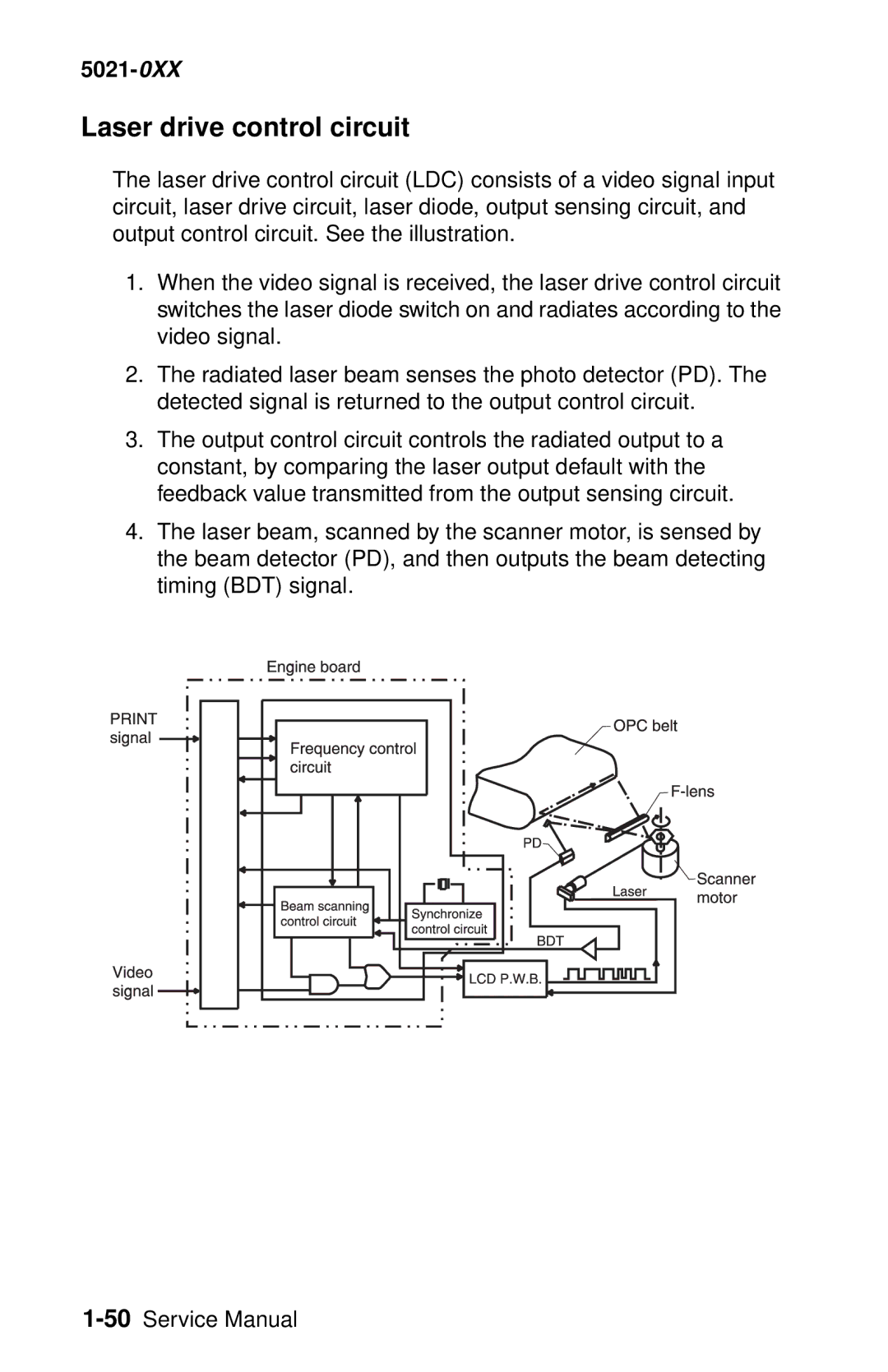
Laser drive control circuit
Interface type
Interface control
Interface connection
5021-0XX
Diagnostic information
Start
Service error codes
Go to 910-Developer motor service check on
Go to 911-Main motor service check on
Go to 912-Power supply fan service check on
Go to 913-Fuser fan service check on
Go to 920-Fuser thermistor service check on
Go to 921,922,923,924,925-Fuser assembly
Go to 930,931,932-Laser unit assembly service
RIP board. Go to RIP board removal on
Controller board removal on
Panel cable removal on
To RIP board removal on
Board removal on
Download emulations on
Go to 985-Duplex connection error 1 service
Go to 986-Duplex connection error 2 service
Go to 990-Transfer belt unit service check on
Go to 991-Transfer roller clutch service check
Go to 992-Transfer belt cleaning roller clutch
Go to 993-Fuser clutch service check on
Cover open service check
Paper size sensing service
Operator messages
5021-0XX
Performing Self Test
Go to Output tray full
TMA
Empty service check on
Cartridge service check on
To Incorrect media service
To Paper size sensing
5021-0XX
Insufficient Memory and Held
Memory may be defective
5021-0XX
Configuration Change
Missing service check on
Waste toner bottle service
Assembly removal on
Fuser assembly removal
Engine controller board
Removal on
Go to Toner low/empty
Paper jam messages
Paper guide C assembly
Paper exit assembly removal on
Board. See I/O board removal
Engine controller board removal
See Duplex unit assembly
Problem, see Paper feed service
Assembly. See Secondary paper
Feed assembly removal on
Symptom tables
Printer symptom table
See White band service check
See Printer no power service
See Waste toner feed service
See Service error codes on
Print quality symptom table
See Mottle service check on
See Residual image service
See Insufficient gloss service
See Back stain service check on
Printer service checks
Yellow developer clutch service check
Interlock switch Locations on
Magenta developer clutch service check
5021-0XX
Cyan developer clutch service check
5021-0XX
Black developer clutch service check
5021-0XX
Yellow toner retract solenoid service check
Engine Controller Board removal
Magenta toner retract solenoid service check
5021-0XX
Cyan toner retract solenoid service check
5021-0XX
Black toner retract solenoid service check
5021-0XX
Developer motor service check
See Developer
Motor removal
4-32. Go
Switch locations on
On page 4-70for steps to
4-57. Go
Board cage
See Engine
Main motor service check
Fuser
Main motor
Assembly
4-38. Go
Board removal
Power supply fan service check
Power supply
Interlock switch
Fan removal on
Fuser fan service check
Interlock switch Cover assembly
See Rear
Locations on Removal on
Interlock switch Removal on
Laser fan service check
Laser unit fan
Erase lamp Removal on
Erase lamp service check
Erase lamp
5021-0XX
See Engine controller Board removal on
Toner empty sensor sender-TPD service check
Sensor sender removal On page 4-35for steps
Toner empty sensor receiver-TTR service check
See Engine controller
Toner sensor
Receiver
Hvps connection service check
Lower feed unit secondary paper assembly service check
Right cover removal on
See Fuser assembly
Fuser thermistor service check
Removal on See Engine
921,922,923,924,925-Fuser assembly service check
930,931,932-Laser unit assembly service check
Laser unit
Printhead
Removal on 4-24. Go
Duplex connection error 1 service check
Duplex connection error 2 service check
Transfer belt unit service check
Transfer belt
Unit removal
Bracket
For 5 VDC from pin 9 to Replace faulty
Clutch
Transfer roller clutch service check
On page 4-70. If
Cleaning roller
Transfer belt cleaning roller clutch service check
Clutch removal
Fuser clutch service check
Right cover removal on Clutch
OPC belt marker sensor service check
Removal on page 4-70for
Marker sensor
4-69. If
For 5 VDC from pin 11 to Replace faulty
High voltage power supply Hvps service check
Photodevelop
Er cartridge
Photodeveloper Cartridge removal On page 4-11 . Has
High voltage Power supply Hvps removal On page 4-59. Has
Voltage power supply Lvps with cage Removal on
Low voltage power supply Lvps service check
Controller board removal Board removal On page 4-55. Does
Cover open service check
Cable that connects to
Cover interlock switch pin
Incorrect media service check
Paper guide
With cage Removal on
High voltage Power supply
Missing photodeveloper cartridge service check
Photodevelop Er cartridge
Missing toner cartridge service check
Present sensor
Board removal See Toner
On page 4-70. If Present sensor
OPC belt photodeveloper cartridge drive service check
Motor Gear assembly Assembly Removal on
Photodevelop Er cartridge Removal on
See Main See Main drive
Controller board removal On page 4-55. Does
Operator panel service check
RIP board Removal on
Output tray full service check
On page 4-70. If Assembly
See Paper exit
Board removal See Paper exit
9 to output tray full
Paper size sensing service check
Left tray guide
Printer no power service check
Operator
Board cage removal on
4-60for
Developer Retract solenoid Drive assembly Cam Removal on
Toner feed service check
See Developer Motor removal
Toner low/empty service check
On page 4-70. Does error See Engine
Sensor sender
4-35and
Transfer roller missing service check
Hvps cage
4-62and
Registration
5021-0XX
Tray empty service check
On page 4-70. If Paper guide
Assembly removal on Paper guide
See Paper guide C
Waste toner bottle service check
Waste toner
Bottle holder
Bottle holder removal on
Waste toner feed service check
Printer paper feed service check
Paper feed service checks
Registration assembly removal on
5021-0XX
Print quality service checks
Background service check
Background is smeared due to toner spread
Photodeveloper cartridge
Back stain service check
Backside of paper is stained
Banding line appears in horizontal direction
Banding service check
See Photodeveloper cartridge
Black line service check
Fine black line appears in printer image
Color misregistration service check
Color misregistration between two colors
Transfer belt unit removal on
Insufficient fusing service check
Printed image is partially missing
Insufficient gloss service check
Gloss on paper is not sufficient
Jitter service check
Main motor assembly removal on
Assembly. See Developer drive
Cartridge removal on
Missing image at edge service check
Image has missing or peeling toner at edge
Mixed color image service check
Mixed color image appears
Clutch removal on
Toner retract solenoid and cam
Mottle service check
Voltage power supply Hvps
Variation of optical density is found in image
See Transfer roller removal on
See Transfer belt cleaning roller
Residual image service check
Image of preceding page appears on every other
Ribbing service check
Light print occurs in right or left side of image
Solenoid and cam removal on
Toner drop service check
Auger removal on
Waste toner feeder removal on
Removal on page 4-6 . Prior to
Toner cartridge Replace faulty toner cartridge
Vertical line service check
Vertical line appears in printed image
Laser unit assembly printhead
Vertical staggering image service check
Printed image staggers in vertical direction
Vertical white band service check
White band appears in vertical direction of printed image
White band service check
Horizontal white banding creates missing portion of image
Transfer roller removal on
See Clutch removal on
White line I service check
Print quality test pages on
White line II service check
White spot and black spot appear on paper
White spot / black spot service check
Belt unit see Transfer belt unit
White print service check
Reinstall. See Transfer roller
Removal on page 4-8 . Ensure
System. See Toner retract solenoid
Wrinkle / image migration service check
Uneven density right and left
Transfer belt unit Replace faulty transfer belt unit. See
Roller specifications
Spacing table
5021-0XX
Select the Disable Option
Disabling download emulations
Paper jam sequence
Go to Paper jam messages on page 2-22for more information
5021-0XX Paper Jam
Diagnostic mode
Print quality test pages
Diagnostics menu structure
Print Quality Description
Print registration
Setting tray 2 left margin
Select Registration Select Left Margin Adj
Setting top margin
Print tests
Select Registration Select Top Margin
Menu
Select Single or Continuous
Hardware tests
Following hardware tests can be selected from this menu
Button test
LCD test
Parallel wrap test
ROM memory test
Dram memory test
Serial wrap test
Transmit Data Interrupt Error
Duplex left margin
Duplex tests
Select Duplex Test Select Duplex Left Margin
Device tests
Disk test/clean
Quick disk test
Flash test
Printer setup
Setting the page count
Viewing the permanent page count
Select either Color Page Counts or Mono Page Counts
Setting configuration ID
Serial number
Parallel strobe adjustment
Viewing the error log
Error log
Printing the error log
Clearing the error log
Restore EP factory defaults
Exiting diagnostic mode
5021-0XX
Removal and cleaning precautions
Repair information
During replacement
Handling the printed circuit boards with MOS ICs
During transportation/storage
During inspection
Handling
Photodeveloper cartridge
Parts not to be touched
Printer removal procedures
Precautions to take before maintenance work
CRU/FRU and supplies removals
Cleaning roller cover removal
Transfer belt cleaning roller removal
Transfer belt unit removal
Transfer roller removal
Fuser assembly removal
Waste toner bottle removal
Open front cover Remove waste toner bottle
Photodeveloper cartridge removal
5021-0XX
Duplex unit assembly removal
5021-0XX
Lift duplex unit up and away from printer Repair information
Secondary paper feed assembly removal
Cover removals
Top cover assembly removal
Front cover assembly removal
5021-0XX
5021-0XX
Rear cover assembly removal
Right cover removal
5021-0XX
Laser unit assembly printhead removal
Left cover removal
5021-0XX
Laser unit fan assembly removal
Erase lamp removal
5021-0XX
Front door interlock switch removal
Right side removals
5021-0XX
Front door interlock switch with bracket
Developer motor removal
Developer drive assembly removal
Waste toner bottle holder removal
5021-0XX
5021-0XX
Toner sensor sender removal
Cleaning roller clutch removal
5021-0XX
Main motor assembly removal
5021-0XX
Clutch removal
Main drive gear assembly removal
Remove fuser clutch. See Clutch removal on
Remove main drive gear assembly from printer
Waste toner feeder removal
5021-0XX
Rear removals
Bracket assembly removal
RIP board removal
Paper guide assembly removal
Paper guide C assembly removal
Paper feed roller removal
Paper exit assembly removal
Remove two screws C
5021-0XX
Registration assembly removal
Remove transfer roller. See Transfer roller removal on
Left side removals
Operator panel cable removal
Remove left cover. See Left cover removal on
Engine controller board removal
5021-0XX
RIP board cage removal
Remove ducting
High voltage power supply Hvps removal
Disconnect all connectors from Hvps Repair information
Low voltage power supply Lvps with cage removal
5021-0XX
Remove HVPS. See High voltage power supply Hvps removal on
Hvps cage removal
Toner present sensor removal
Remove four screws C remove Hvps cage
Toner sensor receiver removal
Toner retract solenoid and cam removal
Left tray guide assembly removal
5021-0XX
5021-0XX
Top removals
Marker sensor assembly removal
Board removal
Do not remove the jumper
Waste toner auger removal
Waste toner agitator removal
Power supply fan removal
Locations and connectors
Printer
Part name Description
Options
Electronic components
Sensor locations
TNK
Printer circuit board locations
Name Function
Fan/motor locations
Interlock switch locations
Solenoid/clutch locations
Fbcl
Toner retract
Symbol and part name table
Symbol Part name
LDU
TTR Trcm
Wiring diagram / cable harness reference
RIP board
Engine controller board
Input/output I/O board
5021-0XX
Printer cables
Engine controller board I1CN-I/O board DCN1
5021-0XX
OAD1 OAD2 Sgnd
Engine controller board I2CN-I/O board DCN3
DCN3
5021-0XX
Engine controller board HVCN-HVPS CN1
Hvcn
Engine controller board P2CN-Operator panel
Board DCN13-LVPS ACN1
Board DCN18-Interlock switches
Lvps ACN2-Interlock switches
Interlock switches-Interlock switches
Lvps ACN5-Engine controller board DCN21
Lvps ACN5-Engine controller board Lvcn
No connection
Engine controller board POCN-LVPS ACN3
ACN3
Board DCN4-Toner retract solenoids
DCN4
Board DCN8-Laser fan
5021-0XX Board DCN5-Photodeveloper OPC marker sensor
Board DCN15-Toner present sensor, erase lamp
Tleschk Sgnd
Board DCN16-Sensors
DCN16
Board DCN7-Rear cover assembly
DCN7
Htfanerr
DCN10
DCLCON-N
5021-0XX Board DCN11-Developer motor
Board DCN12-Main motor
Mmenc MMREV-N Mmgain Mmovld
Engine board LCN-Printhead LDU
LDU
Sgnd SCMRDY-N Scmclk Pgnd SCMON-N
Board DCN14-Lower feeder unit
DCN14
LFCN-CHK-N
Board DCN19-Paper size sensor and temperature thermistor
DCN19
Fuser connector-LVPS 120V Printer
Fuser connector-LVPS 240V Printer
Engine controller board FUCN-fuser
Lvps ACN4-Duplex unit Dupl and duplex power
5021-0XX Engine controller board DPCN-Duplex unit Dupl
Duplex
Preventive maintenance
5021-0XX
How to use this parts catalog
Parts catalog
Assembly 1 Base printer
Assembly 1 Base printer
Index Units Description
Assembly 2 Covers
Assembly 2 Covers
Assembly 3 Front
Assembly 3 Front
Assembly 4 Right
Assembly 4 Right
Assembly 5 Rear
Assembly 5 Rear
Assembly 6 Left
Assembly 6 Left
Assembly 7 Top
Assembly 7 Top
Assembly 8 RIP board
Assembly 8 RIP board
Assembly 9 Miscellaneous/Options
Assembly 9 Miscellaneous/Options
DIMM, 128MB Sdram
Assembly 9 Miscellaneous/Options
Index
Paper transportation system
5021-0XX
5021-0XX
Part number index
5021-0XX
5021-0XX
5021-0XX