OPERATION
| REAR CONNECTIONS |
|
7 | 1 | 2 |
|
![]() WARNING
WARNING
ELECTRODE
V ![]()
![]()
WORK
6 | 5 | 4 | 3 |
FIGURE 8
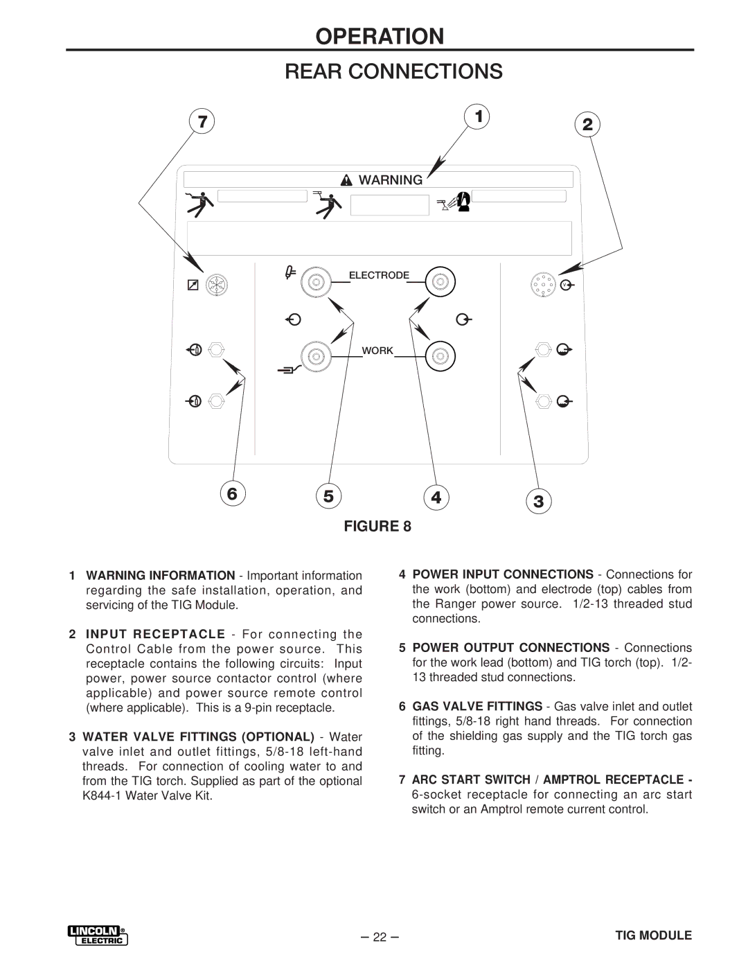
1WARNING INFORMATION - Important information regarding the safe installation, operation, and servicing of the TIG Module.
2INPUT RECEPTACLE - For connecting the Control Cable from the power source. This receptacle contains the following circuits: Input power, power source contactor control (where applicable) and power source remote control (where applicable). This is a
3WATER VALVE FITTINGS (OPTIONAL) - Water valve inlet and outlet fittings,
4POWER INPUT CONNECTIONS - Connections for the work (bottom) and electrode (top) cables from the Ranger power source.
5POWER OUTPUT CONNECTIONS - Connections for the work lead (bottom) and TIG torch (top). 1/2- 13 threaded stud connections.
6GAS VALVE FITTINGS - Gas valve inlet and outlet fittings,
7ARC START SWITCH / AMPTROL RECEPTACLE -
– 22 – | TIG MODULE |