INSTALLATION
Ranger 9 Installation
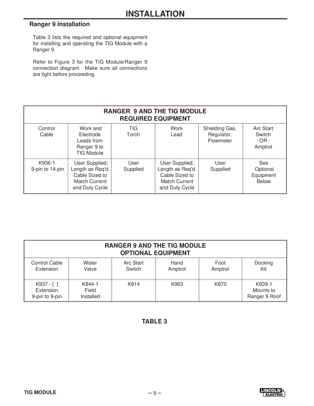
Table 3 lists the required and optional equipment for installing and operating the TIG Module with a Ranger 9.
Refer to Figure 3 for the TIG Module/Ranger 9 connection diagram. Make sure all connections are tight before proceeding.
RANGER 9 AND THE TIG MODULE
REQUIRED EQUIPMENT
|
|
|
|
|
|
|
|
| Control | Work and | TIG | Work | Shielding Gas, | Arc Start |
|
| Cable | Electrode | Torch | Lead | Regulator, | Switch |
|
|
| Leads from |
|
| Flowmeter | - OR - |
|
|
| Ranger 9 to |
|
|
| Amptrol |
|
|
| TIG Module |
|
|
|
|
|
|
|
|
|
|
|
|
|
|
|
|
|
|
|
|
|
| User Supplied; | User | User Supplied; | User | See | ||
| Length as Req’d. | Supplied | Length as Req’d. | Supplied | Optional |
| |
|
| Cable Sized to |
| Cable Sized to |
| Equipment |
|
|
| Match Current |
| Match Current |
| Below |
|
|
| and Duty Cycle |
| and Duty Cycle |
|
|
|
|
|
|
|
|
|
|
|
RANGER 9 AND THE TIG MODULE
OPTIONAL EQUIPMENT
|
|
|
|
|
|
|
|
| Control Cable | Water | Arc Start | Hand | Foot | Docking |
|
| Extension | Valve | Switch | Amptrol | Amptrol | Kit |
|
|
|
|
|
|
|
|
|
|
|
|
|
|
|
|
|
|
|
|
|
|
|
|
|
| K937 - [ ] | K814 | K963 | K870 | |||
| Extension | Field |
|
|
| Mounts to |
|
| Installed |
|
|
| Ranger 9 Roof |
| |
|
|
|
|
|
|
|
|
TABLE 3
TIG MODULE | – 9 – |