INSTALLATION
INSTALLATION WITH A POWER SOURCE
Ranger 8 Installation
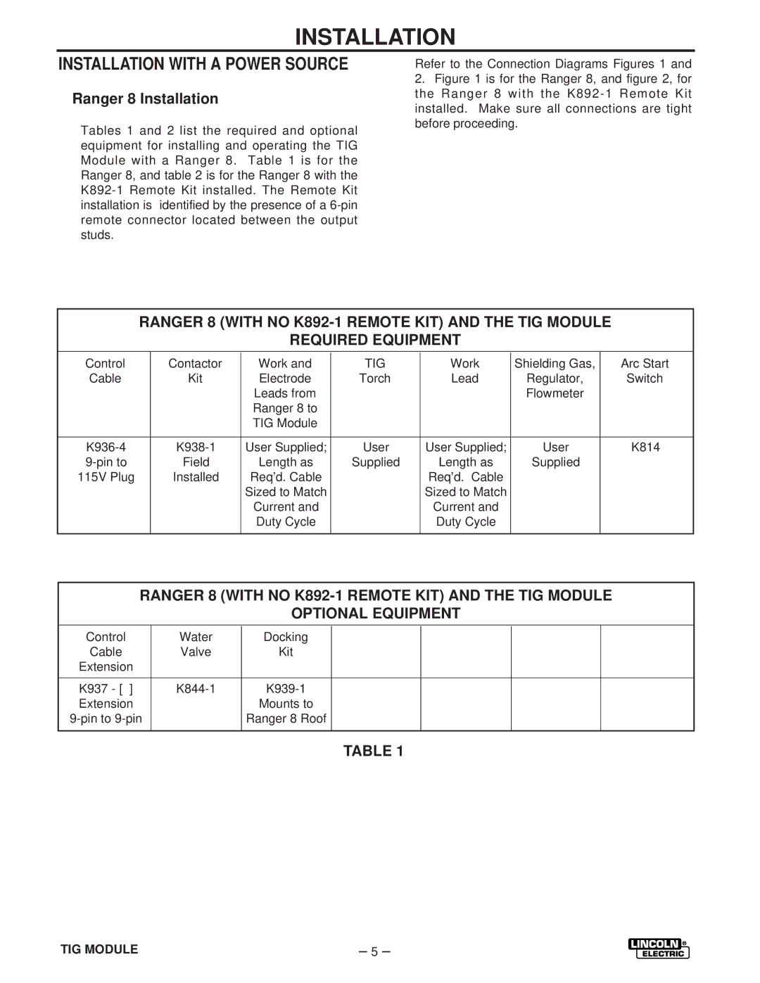
Tables 1 and 2 list the required and optional equipment for installing and operating the TIG Module with a Ranger 8. Table 1 is for the Ranger 8, and table 2 is for the Ranger 8 with the
Refer to the Connection Diagrams Figures 1 and
2.Figure 1 is for the Ranger 8, and figure 2, for the Ranger 8 with the K892-1 Remote Kit installed. Make sure all connections are tight before proceeding.
RANGER 8 (WITH NO
REQUIRED EQUIPMENT
|
|
|
|
|
|
|
|
|
| Control | Contactor | Work and | TIG | Work | Shielding Gas, | Arc Start |
|
| Cable | Kit | Electrode | Torch | Lead | Regulator, | Switch |
|
|
|
| Leads from |
|
| Flowmeter |
|
|
|
|
| Ranger 8 to |
|
|
|
|
|
|
|
| TIG Module |
|
|
|
|
|
|
|
|
|
|
|
|
|
|
|
|
|
|
|
|
|
|
|
| User Supplied; | User | User Supplied; | User | K814 | |||
| Field | Length as | Supplied | Length as | Supplied |
|
| |
| 115V Plug | Installed | Req’d. Cable |
| Req’d. Cable |
|
|
|
|
|
| Sized to Match |
| Sized to Match |
|
|
|
|
|
| Current and |
| Current and |
|
|
|
|
|
| Duty Cycle |
| Duty Cycle |
|
|
|
|
|
|
|
|
|
|
|
|
|
|
|
|
|
|
|
|
|
RANGER 8 (WITH NO
OPTIONAL EQUIPMENT
|
|
|
|
|
|
|
|
|
| Control | Water | Docking |
|
|
|
|
|
| Cable | Valve | Kit |
|
|
|
|
|
| Extension |
|
|
|
|
|
|
|
|
|
|
|
|
|
|
|
|
|
|
|
|
|
|
|
|
|
|
|
|
|
|
|
|
|
|
| K937 - [ ] |
|
|
|
| |||
| Extension |
| Mounts to |
|
|
|
|
|
|
| Ranger 8 Roof |
|
|
|
|
| |
|
|
|
|
|
|
|
|
|
TABLE 1
TIG MODULE | – 5 – |