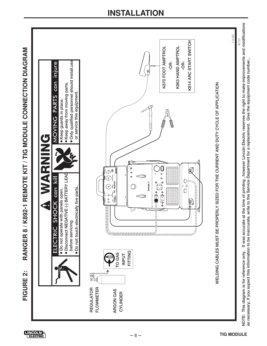
FIGURE 2: RANGER 8 / K892-1 REMOTE KIT / TIG MODULE CONNECTION DIAGRAM
![]() WARNING
WARNING
![]() Do not operate with panels open.
Do not operate with panels open.
![]() Disconnect NEGATIVE
Disconnect NEGATIVE
![]() Do not touch electrically live parts.
Do not touch electrically live parts.
REGULATOR
FLOWMETER
![]() Keep guards in place.
Keep guards in place.
![]() Keep away from moving parts.
Keep away from moving parts.
![]() Only qualified personnel should install,use or service this equipment.
Only qualified personnel should install,use or service this equipment.
– 8 –
ARGON GAS CYLINDER
TO GAS
INPUT FITTING
| O |
|
|
|
| HF |
|
| CURRENT |
POWER | HIGH FREQUENCY | AFTERFLOW | CURRENT CONTROL | CONTROL |
|
|
|
| SWITCH |
LINCOLN |
|
|
| |
ELECTRIC |
|
| WARNING | |
K870 FOOT AMPTROL
K963 HAND AMPTROL
K814 ARC START SWITCH
INSTALLATION
TIG MODULE
WELDING CABLES MUST BE PROPERLY SIZED FOR THE CURRENT AND DUTY CYCLE OF APPLICATION
M17531
NOTE: This diagram is for reference only. It was accurate at the time of printing , however Lincoln Electric reserves the right to make improvements and modifications as necessary, if you supect this information to be inaccurate, write to the Service Department for a replacement. Give the equipment code number..