ACCESSORIES
Idle Roll Pressure Setting
The idle roll pressure is set at the factory, backed out three turns from full pressure on
1)Release the incoming idle roll pressure arm, then press end of gun against a solid object that is elec- trically isolated from the welder output and press the gun trigger for several seconds.
2)Adjust gas supply flow rate for a level higher than will be required, then adjust Gas Guard flow adjust- ing key counterclockwise to the desired gas flow
rate.
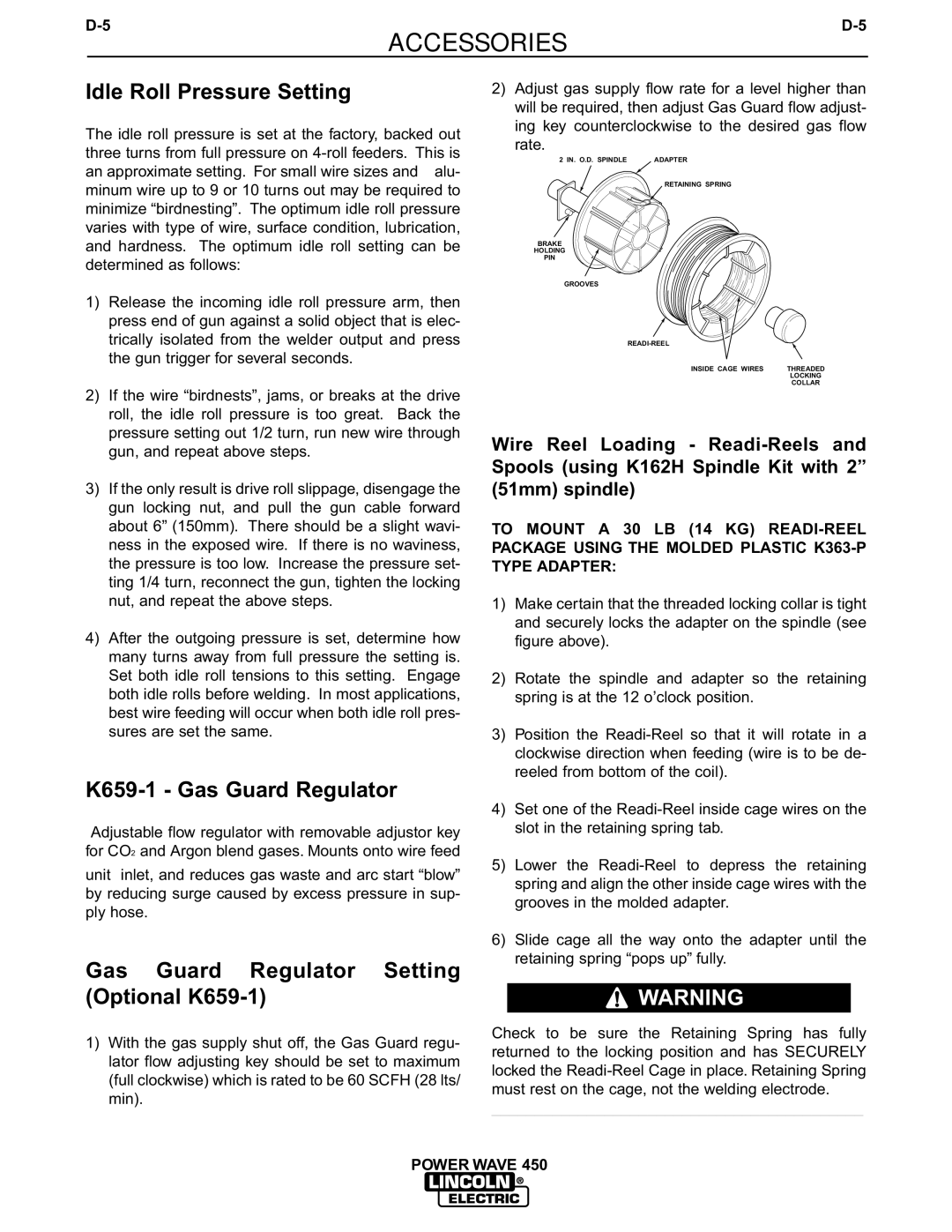
2 IN. O.D. SPINDLE | ADAPTER |
RETAINING SPRING
BRAKE
HOLDING
PIN
GROOVES
INSIDE CAGE WIRES | THREADED |
| LOCKING |
| COLLAR |
2)If the wire “birdnests”, jams, or breaks at the drive roll, the idle roll pressure is too great. Back the pressure setting out 1/2 turn, run new wire through gun, and repeat above steps.
3)If the only result is drive roll slippage, disengage the gun locking nut, and pull the gun cable forward about 6” (150mm). There should be a slight wavi- ness in the exposed wire. If there is no waviness, the pressure is too low. Increase the pressure set- ting 1/4 turn, reconnect the gun, tighten the locking nut, and repeat the above steps.
4)After the outgoing pressure is set, determine how many turns away from full pressure the setting is. Set both idle roll tensions to this setting. Engage both idle rolls before welding. In most applications, best wire feeding will occur when both idle roll pres- sures are set the same.
Wire Reel Loading -
TO MOUNT A 30 LB (14 KG)
1)Make certain that the threaded locking collar is tight and securely locks the adapter on the spindle (see figure above).
2)Rotate the spindle and adapter so the retaining spring is at the 12 o’clock position.
3)Position the
K659-1 - Gas Guard Regulator
Adjustable flow regulator with removable adjustor key for CO2 and Argon blend gases. Mounts onto wire feed
unit inlet, and reduces gas waste and arc start “blow” by reducing surge caused by excess pressure in sup- ply hose.
Gas Guard Regulator Setting (Optional K659-1)
1)With the gas supply shut off, the Gas Guard regu- lator flow adjusting key should be set to maximum (full clockwise) which is rated to be 60 SCFH (28 lts/ min).
4)Set one of the
5)Lower the
6)Slide cage all the way onto the adapter until the retaining spring “pops up” fully.
![]() WARNING
WARNING
Check to be sure the Retaining Spring has fully returned to the locking position and has SECURELY locked the
___________________________________________