ACCESSORIES
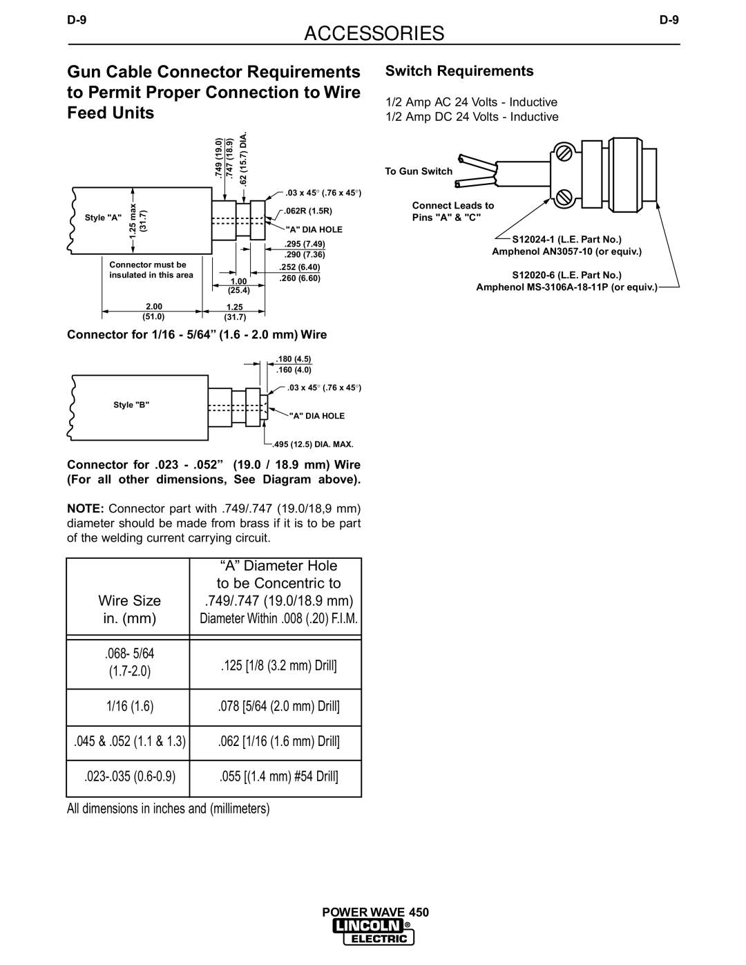
Gun Cable Connector Requirements to Permit Proper Connection to Wire Feed Units
.749 (19.0) | .747 (18.9) | .62 (15.7) DIA. |
![]() .03 x 45° (.76 x 45°)
.03 x 45° (.76 x 45°)
max1.25 | (31.7) | .062R (1.5R) |
Style "A" |
|
|
|
| "A" DIA HOLE |
|
| .295 (7.49) |
Connector must be |
| .290 (7.36) |
| .252 (6.40) | |
insulated in this area | 1.00 | .260 (6.60) |
| (25.4) |
|
2.00 | 1.25 |
|
(51.0) | (31.7) |
|
Switch Requirements
1/2 Amp AC 24 Volts - Inductive
1/2 Amp DC 24 Volts - Inductive
To Gun Switch
Connect Leads to
Pins "A" & "C"
Amphenol
Amphenol
Connector for 1/16 - 5/64” (1.6 - 2.0 mm) Wire
Style "B"
.180 (4.5)
.160 (4.0)
![]() .03 x 45° (.76 x 45°)
.03 x 45° (.76 x 45°)
![]() "A" DIA HOLE
"A" DIA HOLE
.495 (12.5) DIA. MAX.
Connector for .023
NOTE: Connector part with .749/.747 (19.0/18,9 mm) diameter should be made from brass if it is to be part of the welding current carrying circuit.
| “A” Diameter Hole | |
Wire Size | to be Concentric to | |
.749/.747 (19.0/18.9 mm) | ||
in. (mm) | Diameter Within .008 (.20) F.I.M. | |
|
| |
|
| |
.068- 5/64 | .125 [1/8 (3.2 mm) Drill] | |
|
1/16 (1.6)
.078 [5/64 (2.0 mm) Drill]
.045 & .052 (1.1 & 1.3)
.062 [1/16 (1.6 mm) Drill]
.055 [(1.4 mm) #54 Drill]
All dimensions in inches and (millimeters)