INSTALLATION | ||
|
|
|
ExAMPLES OF CONNECTING AN ARCLINK POWER WAVE SYSTEM
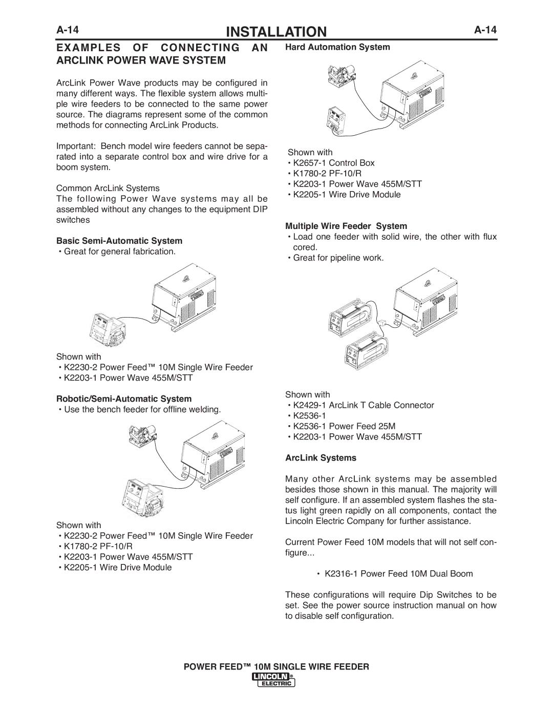
ArcLink Power Wave products may be configured in many different ways. The flexible system allows multi- ple wire feeders to be connected to the same power source. The diagrams represent some of the common methods for connecting ArcLink Products.
Important: Bench model wire feeders cannot be sepa- rated into a separate control box and wire drive for a boom system.
Common ArcLink Systems
The following Power Wave systems may all be assembled without any changes to the equipment DIP switches
basic Semi-Automatic System
• Great for general fabrication.
Shown with
•
•
Robotic/Semi-Automatic System
• Use the bench feeder for offline welding.
Shown with
•
•
•
•
Hard Automation System
Shown with
•
•
•
•
Multiple Wire Feeder System
•Load one feeder with solid wire, the other with flux cored.
•Great for pipeline work.
Shown with
•
•
•
•
ArcLink Systems
Many other ArcLink systems may be assembled besides those shown in this manual. The majority will self configure. If an assembled system flashes the sta- tus light green rapidly on all components, contact the Lincoln Electric Company for further assistance.
Current Power Feed 10M models that will not self con-
figure...
•
These configurations will require Dip Switches to be set. See the power source instruction manual on how to disable self configuration.
