Return to Master TOC
Return to Master TOC
Section
TABLE OF CONTENTS
-THEORY OF OPERATION SECTION-
Theory of Operation | Section E |
General Description | |
Input Line Voltage, Auxiliary Transformer and Precharge | |
Switch Board and Main Transformer | |
DC Bus Board, Power board and Control Board | |
Output Rectifier and Choke | |
Thermal Protection | |
Protective Circuits | |
Over current Protection | |
Under/Over Voltage Protection | |
Insulated Gate Bipolar Transistor (IGBT) Operation | |
Pulse Width Modulation | |
Minimum/Maximum Output |
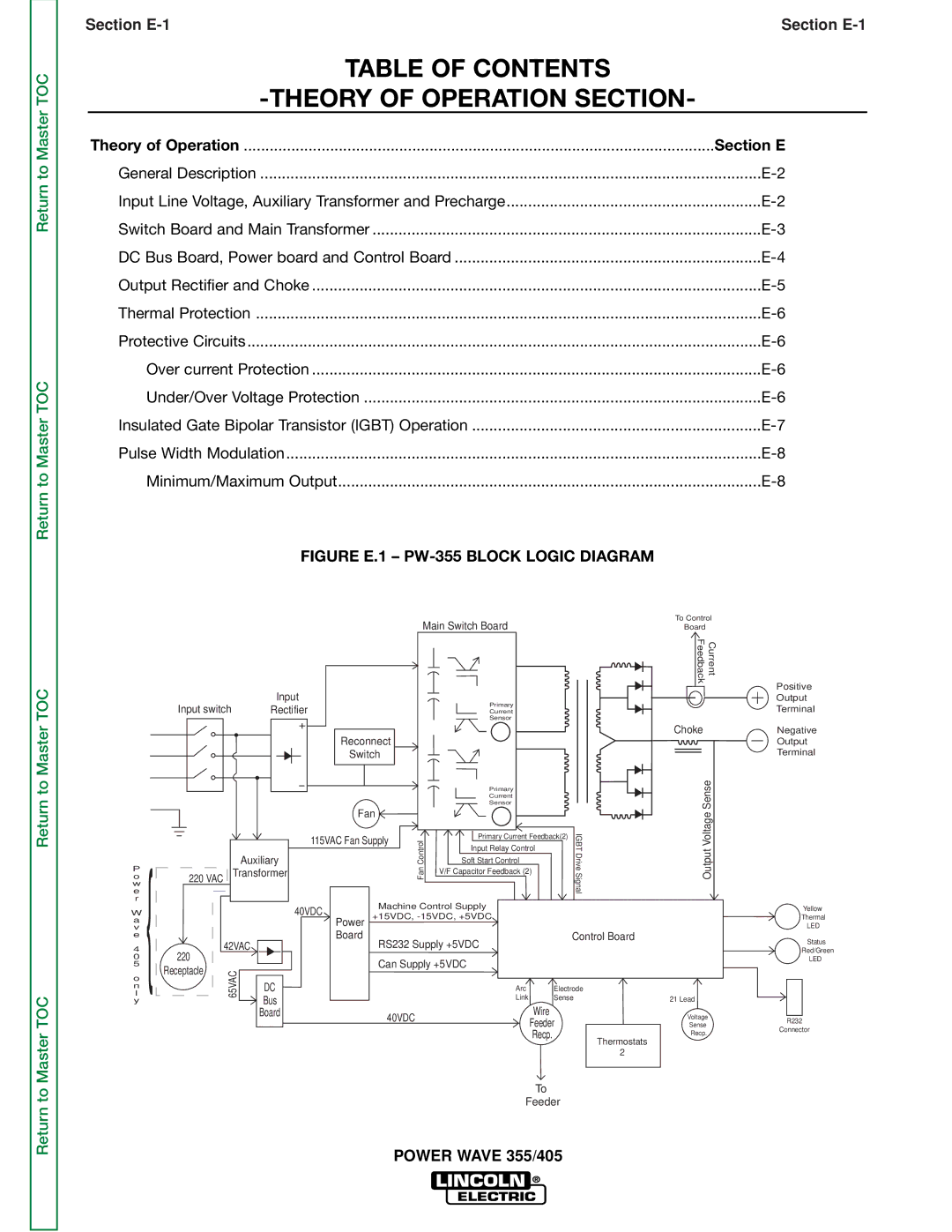
FIGURE E.1 – PW-355 BLOCK LOGIC DIAGRAM
Return to Master TOC
Return to Master TOC
Main Switch Board
Input
|
| Input switch | Rectifier |
|
| Primary |
|
| |
|
|
|
| Current |
|
| |||
|
|
|
|
|
|
| Sensor |
|
|
|
|
|
| Reconnect |
|
|
|
| |
|
|
|
| Switch |
|
|
|
| |
|
|
|
|
|
|
| Primary |
|
|
|
|
|
|
|
|
| Current |
|
|
|
|
|
|
|
|
| Sensor |
|
|
|
|
|
| Fan |
|
|
|
| |
e |
|
|
| 115VAC Fan Supply | CanFontrol | Primary Current Feedback(2) | IGBTDriveignalS | ||
{ |
|
| Input Relay Control |
| |||||
|
|
|
|
|
| ||||
|
|
|
|
|
|
|
| ||
P |
|
| Auxiliary |
|
| Soft Start Control |
|
| |
220 VAC Transformer |
|
| V/F Capacitor Feedback (2) |
|
| ||||
o |
|
|
|
|
| ||||
w |
|
|
|
|
|
|
|
| |
r |
|
|
| Machine Control Supply |
|
| |||
W |
|
| 40VDC |
|
| ||||
|
| +15VDC, |
|
| |||||
a |
|
| Power |
|
| ||||
v |
|
| Board |
|
|
| Control Board | ||
e |
|
| RS232 Supply +5VDC | ||||||
4 | 220 | 42VAC |
|
| |||||
0 |
|
| Can Supply +5VDC |
|
| ||||
5 | Receptacle | 65VAC |
|
|
| ||||
l | DC |
|
| Arc | Electrode | ||||
o |
|
|
|
|
|
|
|
|
|
n |
|
|
|
|
|
|
|
|
|
y |
|
|
| Bus |
|
| Link | Sense |
|
|
|
|
| Board | 40VDC |
| Wire |
|
|
|
|
|
|
|
| Feeder |
| ||
|
|
|
|
|
|
|
| ||
|
|
|
|
|
|
| Recp. |
| Thermostats |
|
|
|
|
|
|
|
|
| |
|
|
|
|
|
|
|
|
| 2 |
|
|
|
|
|
|
| To |
|
|
|
|
|
|
|
|
| Feeder |
| |
POWER WAVE 355/405
To Control
Board
Feedback | Current |
Choke
SenseVoltage
Output
21 Lead
Voltage
Sense
Recp.
Positive
Output
Terminal
Negative
Output
Terminal
Yellow
Thermal
LED
Status
Red/Green
LED
R232
Connector