TOC
TOC
TROUBLESHOOTING & REPAIR
INPUT RECTIFIER REMOVAL AND REPLACEMENT (continued)
Return to Section
Return to Master
9.Apply a thin coat of Penetrox
10.Secure the new input bridge into its proper posi- tion with the two 3/16”in. allen mounting screws previously removed. Torque to 44 inch pounds.
11.Reconnect the previously removed leads to their proper locations. Torque to 31 inch pounds.
12.Cover the input rectifier and its six terminals with silicon sealant.
13.Replace the case wraparound cover.
Return to Section TOC
Return to Section TOC
Return to Section TOC
Return to Master TOC
Return to Master TOC
Return to Master TOC
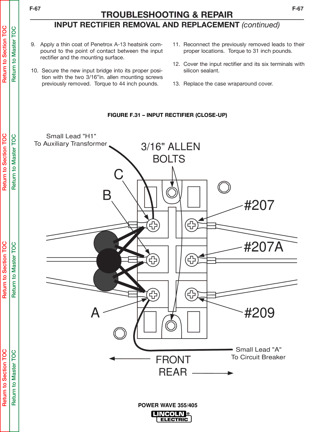
FIGURE F.31 – INPUT RECTIFIER (CLOSE-UP)
Small Lead "H1" |
|
To Auxiliary Transformer | 3/16" ALLEN |
| |
| BOLTS |
C
B
#207
 #207A
#207A
A | #209 |
|
| Small Lead "A" |
FRONT |
| To Circuit Breaker |
|
| |
REAR |
|
|
|
|