INSTALLATION
Return to Master TOC
Return to Master TOC
SYSTEM DESCRIPTION
The POWER WAVE 355/405 and Power Feed 10/11 family of products utilize a digital communication sys- tem called
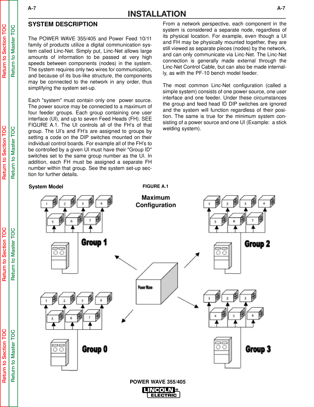
Each "system" must contain only one power source. The power source may be connected to a maximum of four feeder groups. Each group containing one user interface (UI), and up to seven Feed Heads (FH). SEE FIGURE A.1. The UI controls all of the FH’s of that group. The UI’s and FH’s are assigned to groups by setting a code on the DIP switches mounted on their individual control boards. For example all of the FH’s to be controlled by a given UI must have their "Group ID" switches set to the same group number as the UI. In addition, each FH must be assigned a separate FH number within that group. See the system
From a network perspective, each component in the system is considered a separate node, regardless of its physical location. For example, even though a UI and FH may be physically mounted together, they are still viewed as separate pieces (nodes) by the network, and can only communicate via
The most common
Return to Section TOC
Return to Section TOC
Return to Section TOC
Return to Section TOC
Return to Master TOC
Return to Master TOC
System Model | FIGURE A.1 |
Maximum
Configuration
POWER WAVE 355/405