Return to Section TOC
to Section TOC
Return to Master TOC
to Master TOC
THEORY OF OPERATION | ||
|
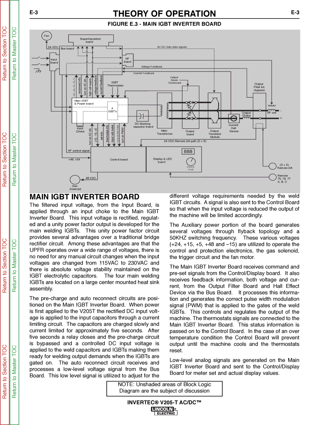
FIGURE E.3 - MAIN IGBT INVERTER BOARD
Fan |
|
|
|
|
|
|
|
|
|
|
|
|
|
|
|
|
| Superimposition |
|
|
|
|
|
|
|
|
| ||||
|
|
| board |
|
|
|
|
|
|
|
|
|
|
| |
24 VDC | Bus board |
|
|
|
|
|
|
|
|
| AC DC Gate drive signals |
|
|
| |
Input |
|
|
|
|
|
|
|
|
| HF |
|
|
|
|
|
|
|
|
|
|
|
|
|
| board |
|
|
|
|
| |
board |
|
|
|
|
|
|
|
|
|
|
|
|
|
| |
|
|
|
|
|
|
|
|
|
|
|
|
|
|
| |
|
|
|
|
|
|
|
|
|
|
| Voltage Feedback |
|
|
|
|
| info.reconnect | .ACcktturnon | supplyvolthigh | feedbackvoltage | feedbackcurrent |
|
|
|
| Current Feedback |
|
|
|
| |
|
|
|
|
| Output |
|
|
|
| ||||||
|
|
|
|
|
|
|
| IGBT |
| Diode |
|
|
|
| |
|
|
|
|
|
|
|
|
| Thermostat |
|
|
| Output | ||
|
|
|
|
|
|
| Thermostats |
|
|
|
| ||||
|
|
|
|
|
|
|
|
|
|
| Filter bd. | ||||
|
|
|
|
|
|
|
|
|
|
|
|
|
|
| |
|
|
|
|
|
|
|
|
|
|
|
|
|
|
| (bypass) |
| Main IGBT |
|
|
|
|
|
|
|
|
|
|
|
| ||
| & Power board |
|
|
|
|
|
|
|
|
|
|
| |||
|
|
|
|
|
|
|
| 4 |
|
|
|
|
|
| _ |
|
|
|
|
|
|
|
| IGBT's |
|
|
|
|
| ||
|
|
|
|
|
|
|
|
|
|
|
| Output | RF coil | ||
|
|
|
|
|
|
|
|
|
|
|
|
|
| ||
|
|
|
|
|
|
|
|
|
|
|
|
|
| Choke | + |
|
|
|
|
|
|
|
|
|
|
|
|
|
|
| |
|
|
|
|
|
|
| infothermostat | metervoltinput | metercurrentinput |
| DC blocking |
|
| Current |
|
|
|
|
| ckt.AConturn | infoset | PWMonturn | capacitor board |
|
|
| |||||
|
| Input |
|
|
| Hall |
| ||||||||
|
|
|
|
|
|
|
|
|
|
|
|
| |||
|
|
|
|
|
|
|
|
|
| Main |
| Output |
| ||
|
| Choke |
|
|
|
|
|
|
| Output | Device |
| |||
|
|
|
|
|
|
|
|
|
|
| Transformer | board | Transistor |
|
|
|
|
|
|
|
|
|
|
|
|
|
|
| Module |
|
|
|
|
|
|
|
|
|
|
|
|
| 24 VDC Remote 2/4 path (D + E) |
|
|
| |
| HF control signal |
|
|
|
|
|
|
| 888 |
|
|
| |||
| +48, +24 |
|
|
|
|
| Control board | Display & LED |
|
|
|
| |||
|
|
|
|
|
|
|
|
|
|
| board |
|
|
|
|
Control | (D + E) | |
Remote 2/4 | ||
Knob | ||
|
Return
Return to Section TOC
to Section TOC
Return
Return to Master TOC
to Master TOC
48 VDC
Gas
Solenoid
MAIN IGBT INVERTER BOARD
The filtered input voltage, from the Input Board, is applied through an input choke to the Main IGBT Inverter Board. This input voltage is rectified, regulat- ed and a unity power factor output is developed for the main welding IGBTs. This unity power factor circuit provides several advantages over a traditional bridge rectifier circuit. Among these advantages are that the UPFR operates over a wide range of voltages, there is no need for any manual circuit changes when the input voltages are changed from 115VAC to 230VAC and there is absolute voltage stability maintained on the IGBT electrolytic capacitors. The four main welding IGBTs are located on a large center mounted heat sink assembly.
The
Remote 75, 76, 77 A, B, C
different voltage requirements needed by the weld IGBT circuits. A signal is also sent to the Control Board so that when the input voltage is reduced the output of the machine will be limited accordingly.
The Auxiliary power portion of the board generates several voltages through flyback topology and a 50KHZ switching frequency. These various voltages (+24, +15, +5, +48 and
The Main IGBT Inverter Board receives command and
Return
Return
NOTE: Unshaded areas of Block Logic Diagram are the subject of discussion