Return to Section TOC
Return to Section TOC
Return to Master TOC
Return to Master TOC
THEORY OF OPERATION | ||
|
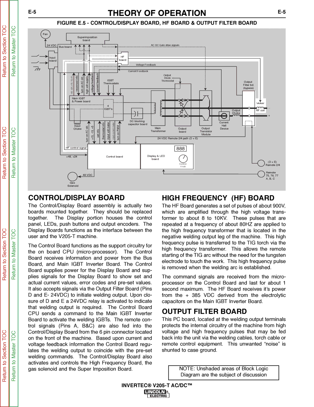
FIGURE E.5 - CONTROL/DISPLAY BOARD, HF BOARD & OUTPUT FILTER BOARD
Fan |
|
|
|
|
|
|
|
|
|
|
|
|
|
|
|
|
| Superimposition |
|
|
|
|
|
|
|
|
| ||||
|
|
| board |
|
|
|
|
|
|
|
|
|
|
| |
24 VDC | Bus board |
|
|
|
|
|
|
|
|
| AC DC Gate drive signals |
|
|
| |
Input |
|
|
|
|
|
|
|
|
| HF |
|
|
|
|
|
|
|
|
|
|
|
|
|
| board |
|
|
|
|
| |
board |
|
|
|
|
|
|
|
|
|
|
|
|
|
| |
|
|
|
|
|
|
|
|
|
|
|
|
|
|
| |
|
|
|
|
|
|
|
|
|
|
| Voltage Feedback |
|
|
|
|
| .inforeconnect | ckt.AConturn | supplyvolthigh | feedbackvoltage | feedbackcurrent |
|
|
|
| Current Feedback |
|
|
|
| |
|
|
|
|
| Output |
|
|
|
| ||||||
|
|
|
|
|
|
|
|
|
|
|
|
|
|
| |
|
|
|
|
|
|
|
| IGBT |
| Diode |
|
|
|
| |
|
|
|
|
|
|
|
|
| Thermostat |
|
|
| Output | ||
|
|
|
|
|
|
| Thermostats |
|
|
|
| ||||
|
|
|
|
|
|
|
|
|
|
| Filter bd. | ||||
|
|
|
|
|
|
|
|
|
|
|
|
|
|
| |
|
|
|
|
|
|
|
|
|
|
|
|
|
|
| (bypass) |
| Main IGBT |
|
|
|
|
|
|
|
|
|
|
|
| ||
| & Power board |
|
|
|
|
|
|
|
|
|
|
| |||
|
|
|
|
|
|
|
| 4 |
|
|
|
|
|
| _ |
|
|
|
|
|
|
|
| IGBT's |
|
|
|
|
| ||
|
|
|
|
|
|
|
|
|
|
|
| Output | RF coil | ||
|
|
|
|
|
|
|
|
|
|
|
|
|
| ||
|
|
|
|
|
|
|
|
|
|
|
|
|
| Choke | + |
|
|
|
|
|
|
|
|
|
|
|
|
|
|
| |
|
|
|
|
|
|
| infothermostat | metervoltinput | metercurrentinput |
| DC blocking |
|
| Current |
|
|
|
|
| .cktAConturn | infoset | PWMonturn | capacitor board |
|
|
| |||||
|
| Input |
|
|
| Hall |
| ||||||||
|
|
|
|
|
|
|
|
|
| Main |
| Output |
| ||
|
| Choke |
|
|
|
|
|
|
| Output | Device |
| |||
|
|
|
|
|
|
|
|
|
|
| Transformer | board | Transistor |
|
|
|
|
|
|
|
|
|
|
|
|
|
|
| Module |
|
|
|
|
|
|
|
|
|
|
|
|
| 24 VDC Remote 2/4 path (D + E) |
|
|
| |
| HF control signal |
|
|
|
|
|
|
| 888 |
|
|
| |||
| +48, +24 |
|
|
|
|
| Control board | Display & LED |
|
|
|
| |||
|
|
|
|
|
|
|
|
|
|
| board |
|
|
|
|
Control | (D + E) | |
Remote 2/4 | ||
Knob | ||
|
Remote
48 VDC75, 76, 77 A, B, C
Gas
Solenoid
Return to Section TOC
Return to Section TOC
Return to Master TOC
Return to Master TOC
CONTROL/DISPLAY BOARD
The Control/Display Board assembly is actually two boards mounted together. They should be replaced together. The Display portion houses the control panel, LEDs, push buttons and output encoders. The Display Boards functions as the interface between the user and the
The Control Board functions as the support circuitry for the on board CPU
HIGH FREQUENCY (HF) BOARD
The HF Board generates a set of pulses of about 900V, which are amplified through the high voltage trans- former to about 8 to 10KV. These pulses that are repeated at a frequency of about 80HZ are applied to the high frequency transformer that is located in the negative welding output leg of the machine. This high frequency pulse is transferred to the TIG torch via the high frequency transformer. This allows the remote starting of the TIG arc without the need for the tungsten electrode to touch the work. This high frequency pulse is removed when the welding arc is established.
The command signals are received from the micro- processor on the Control Board and last for about 1 second maximum. The HF Board receives it’s power from the + 385 VDC derived from the electrolytic capacitors on the Main IGBT Inverter Board.
OUTPUT FILTER BOARD
This PC board, located at the welding output terminals protects the internal circuitry of the machine from high voltage and high frequency pulses that may be fed back into the unit via the welding cables, torch cable or remote control equipment. This unwanted “noise” is shunted to case ground.
NOTE: Unshaded areas of Block Logic
Diagram are the subject of discussion