Return to Section TOC
Return to Section TOC
Return to Master TOC
Return to Master TOC
TROUBLESHOOTING AND REPAIR | ||
|
SECONDARY OUTPUT BOARD ASSEMBLY TEST (continued)
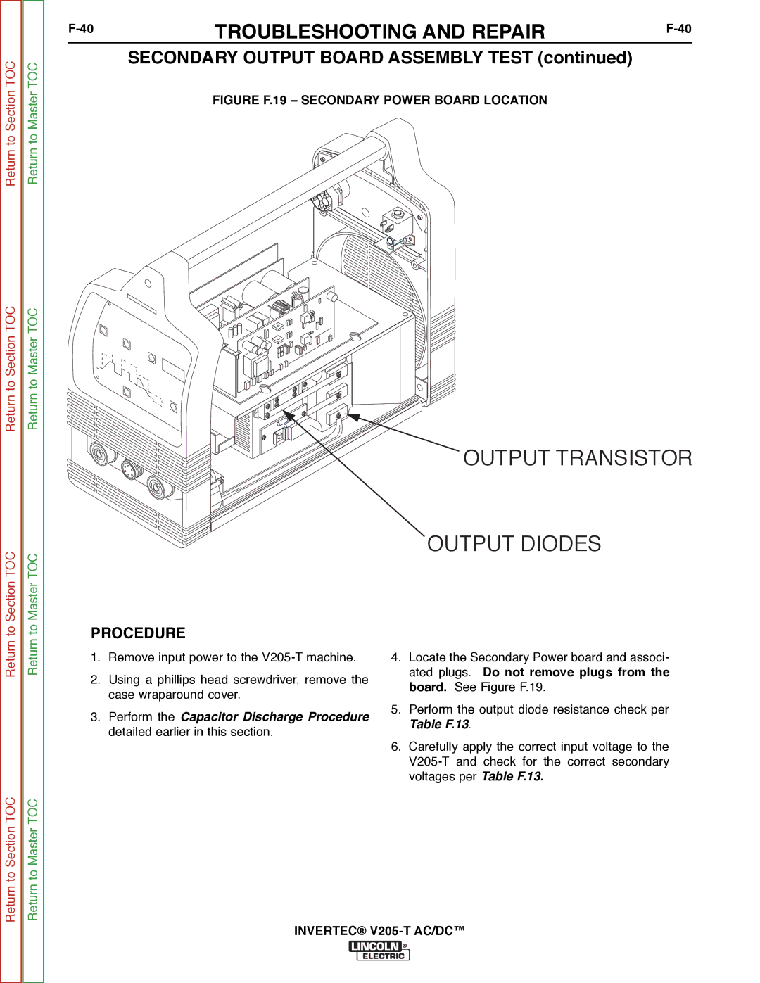
FIGURE F.19 – SECONDARY POWER BOARD LOCATION
Return to Section TOC
Return to Section TOC
Return to Master TOC
Return to Master TOC
PROCEDURE
1.Remove input power to the
2.Using a phillips head screwdriver, remove the case wraparound cover.
3.Perform the Capacitor Discharge Procedure detailed earlier in this section.
OUTPUT TRANSISTOR
OUTPUT DIODES
4.Locate the Secondary Power board and associ- ated plugs. Do not remove plugs from the board. See Figure F.19.
5.Perform the output diode resistance check per Table F.13.
6.Carefully apply the correct input voltage to the