Return to Section TOC
Return to Section TOC
Return to Master TOC
Return to Master TOC
TROUBLESHOOTING AND REPAIR | ||
|
CONTROL/DISPLAY BOARD TEST (continued)
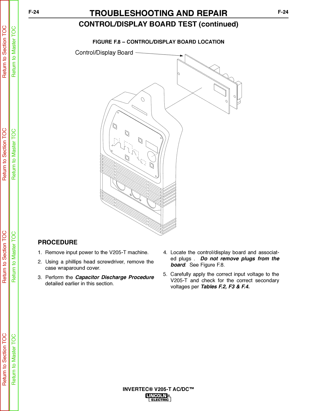
FIGURE F.8 – CONTROL/DISPLAY BOARD LOCATION
Control/Display Board ![]()
Return to Section TOC
Return to Section TOC
Return to Master TOC
Return to Master TOC
PROCEDURE
1.Remove input power to the
2.Using a phillips head screwdriver, remove the case wraparound cover.
3.Perform the Capacitor Discharge Procedure detailed earlier in this section.
4.Locate the control/display board and associat- ed plugs . Do not remove plugs from the board. See Figure F.8.
5.Carefully apply the correct input voltage to the