Return to Section TOC
Return to Section TOC
Return to Section TOC
Return to Section TOC
Return to Master TOC
Return to Master TOC
Return to Master TOC
Return to Master TOC
TROUBLESHOOTING AND REPAIR |
|
|
|
| |||||
|
|
|
|
|
|
|
| ||
|
|
|
|
|
|
| |||
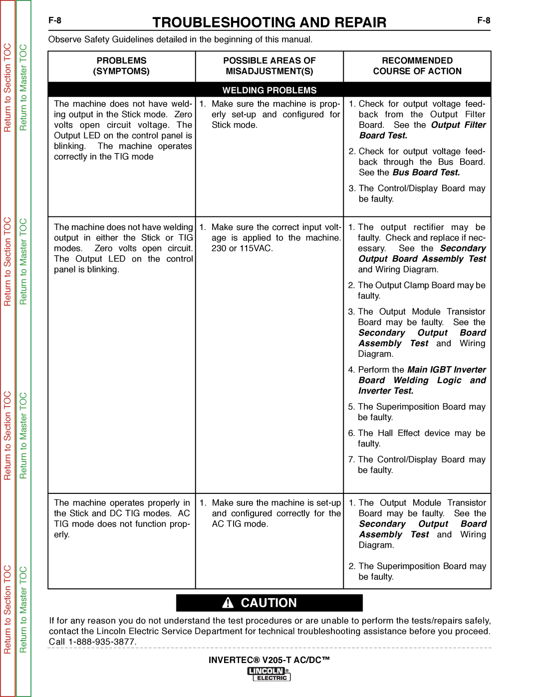
Observe Safety Guidelines detailed in the beginning of this manual. |
|
|
|
|
|
| |||
|
|
|
|
|
|
| |||
| PROBLEMS |
| POSSIBLE AREAS OF | RECOMMENDED |
|
| |||
| (SYMPTOMS) |
| MISADJUSTMENT(S) | COURSE OF ACTION |
| ||||
|
|
|
|
|
|
|
|
|
|
|
|
| WELDING PROBLEMS |
|
|
|
|
|
|
The machine does not have weld- | 1. | Make sure the machine is prop- | 1. Check for output voltage feed- | ||||||
ing output in the Stick mode. Zero |
| erly | back from the Output Filter | ||||||
volts open circuit voltage. The |
| Stick mode. | Board. | See the Output Filter | |||||
Output LED on the control panel is |
|
| Board Test. |
|
|
|
| ||
blinking. | The machine operates |
|
| 2. Check | for output voltage feed- | ||||
correctly in the TIG mode |
|
| |||||||
|
| back through the Bus Board. | |||||||
|
|
|
| ||||||
|
|
|
| See the Bus Board Test. |
| ||||
|
|
|
| 3. The Control/Display Board may | |||||
|
|
|
| be faulty. |
|
|
|
| |
|
|
|
|
|
| ||||
The machine does not have welding | 1. | Make sure the correct input volt- | 1. The output | rectifier may | be | ||||
output in either the Stick or TIG |
| age is applied to the machine. | faulty. Check and replace if nec- | ||||||
modes. | Zero volts open circuit. |
| 230 or 115VAC. | essary. | See the | Secondary | |||
The Output LED on the control |
|
| Output Board Assembly Test | ||||||
panel is blinking. |
|
| and Wiring Diagram. |
|
| ||||
|
|
|
| 2. The Output Clamp Board may be | |||||
|
|
|
| faulty. |
|
|
|
|
|
|
|
|
| 3. The Output | Module Transistor | ||||
|
|
|
| Board may be faulty. See the | |||||
|
|
|
| Secondary | Output | Board | |||
|
|
|
| Assembly | Test | and | Wiring | ||
|
|
|
| Diagram. |
|
|
|
| |
|
|
|
| 4. Perform the Main IGBT Inverter | |||||
|
|
|
| Board | Welding | Logic | and | ||
|
|
|
| Inverter Test. |
|
|
| ||
|
|
|
| 5. The Superimposition Board may | |||||
|
|
|
| be faulty. |
|
|
|
| |
|
|
|
| 6. The Hall Effect device may be | |||||
|
|
|
| faulty. |
|
|
|
|
|
|
|
|
| 7. The Control/Display Board may | |||||
|
|
|
| be faulty. |
|
|
|
| |
|
|
|
|
| |||||
The machine operates properly in | 1. | Make sure the machine is | 1. The Output | Module Transistor | |||||
the Stick and DC TIG modes. AC |
| and configured correctly for the | Board may be faulty. | See the | |||||
TIG mode does not function prop- |
| AC TIG mode. | Secondary | Output | Board | ||||
erly. |
|
|
| Assembly | Test | and | Wiring | ||
|
|
|
| Diagram. |
|
|
|
| |
|
|
|
| 2. The Superimposition Board may | |||||
|
|
|
| be faulty. |
|
|
|
| |
|
|
|
|
|
|
|
|
|
|
![]() CAUTION
CAUTION
If for any reason you do not understand the test procedures or are unable to perform the tests/repairs safely, contact the Lincoln Electric Service Department for technical troubleshooting assistance before you proceed. Call