Ranger 10,000 /10,000 Plus
For Engine
Safety
Powered equipment
ARC Rays can burn
Fumes and Gases
Iii
Welding and Cutting Sparks can cause fire or Explosion
Cylinder may explode If damaged
Précautions DE Sûreté
Master Table of Contents for ALL Sections
Section A-1
Table of Contents
Installation Section
Installation
Height Width Depth Weight
Horsepower Operating Speed RPM
Safety Precautions
Spark Arrester
Machine Grounding
Towing
PRE-OPERATION Service
Gasoline
Vehicle Mounting
Can cause fire or explosion
Welding Output Cables
Total Combined Length of Electrode and Work Cables
Angle of Operation
Lifting
Connection of Lincoln Electric Wire Feeders
Instructions
Stacking
Welder Operation
Auxiliary Power
120/240 Volt Dual Voltage Receptacle
Duplex Receptacles
Motor Starting
These Devices Without Additional Resistive Type Loads
Not USE These Devices With a Ranger 10,000
Simultaneous Welding and Power
Standby Power Connections
Figure A.1
Ranger 10,000 & Ranger 10,000 Plus
Operation
Operation Section
Section B-1
Welder Controls Function and Operation
Engine Switch
Operation
Polarity Switch
Range Switch
Kohler Honda Robin / Subaru 20 H.P. Command
Control Dial
STARTING/SHUTDOWN Instructions
BREAK-IN Period
Starting the Engine
Stopping the Engine
TIG Constant Current Welding
Wire Feed Welding Processes Constant Voltage
Stick Constant Current Welding
Start Switch Wire FEED, LN-15
Summary of Welding Processes
Accessories Section
Section C-1
Accessories
Optional Equipment Field Installed
Recommended Equipment
Stick
TIG Welding
Plasma Cutting
Ranger 10,000 & Ranger 10,000 Plus
Maintenance Section
Section D-1
Kohler Honda
Maintenance
Safety Precautions
AIR Cleaner and Other Maintenance
OIL Filter Change
Engine Adjustments
Battery
Overspeed is Hazardous
Slip Rings
Pre-Cleaner
Oil Filter
Air Filter
Element
Figure D.1 Major Component Location
Theory of Operation
Theory of Operation Section
Section E-1
BATTERY, STARTER, ENGINE, ROTOR, STATOR, and Idler Solenoid
Theory of Operation
Rotor Field Feedback and Auxiliary Power
Figure E.3 Rotor Field Feedback and Auxiliary Power
Weld WINDING, REACTOR, Range Switch
Figure E.4 Weld WINDING, REACTOR, and Range Switch
Output BRIDGE, Choke Polarity SWITCH, and Output Terminals
Ranger 10,000 & Ranger 10,000 Plus
Troubleshooting & Repair Section
Section F-1
Troubleshooting & Repair
HOW to USE Troubleshooting Guide
PC Board Troubleshooting Procedures
Electric Shock
Troubleshooting Guide
Output Problems
Output Problems
Field Winding Voltage Test
Adjustment Test
Troubleshooting Guide
Output Problems
Engine Problems
Make sure the leads are looped
Charging Circuit Test
Welding Problems
Ranger 10,000 & Ranger 10,000 Plus
Materials Needed
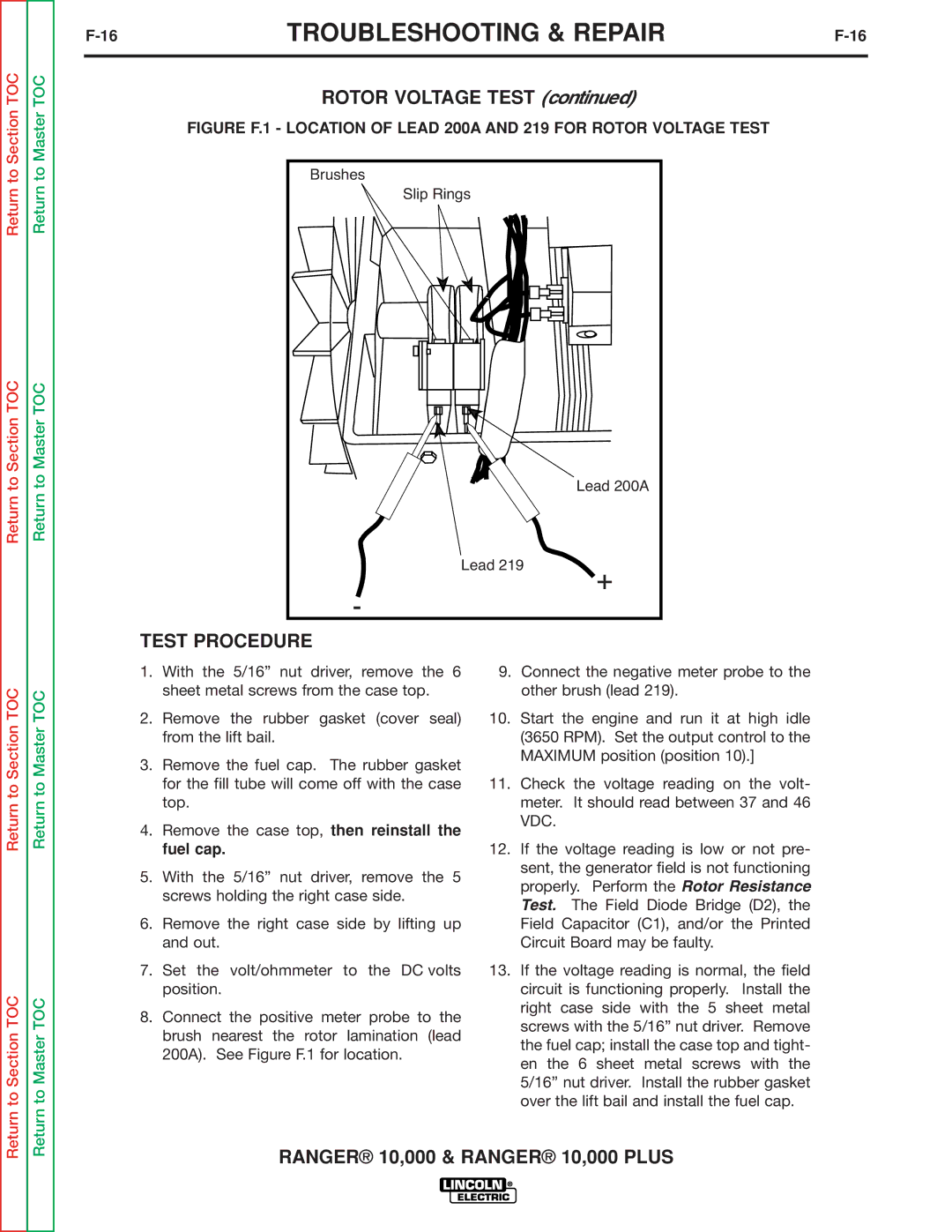
Rotor Voltage Test
Test Description
Test Procedure
Rotor Resistance Test
Rotor Resistance Test
Figure F.2 Location of Rotor Slip Rings
Troubleshooting & Repair
Ranger 10,000 & Ranger 10,000 Plus
Auxiliary and Field Winding Test
To test the 230 VAC winding
Auxiliary and Field Winding Test
To test the 115 VAC winding
To test the field winding
Ranger 10,000 & Ranger 10,000 Plus
Output Rectifier Bridge Test
Figutpure F.4 Locationctifof Output Rectifier Leads
26TROUBLESHOOTING & REPAIRF-26
Output Rectifier Bridge Test
Charging Circuit Test
Charging Circuit Test
Figure F.5 Location of Voltage Regulator
Engine Throttle Adjustment Test
Engine Throttle Adjustment Test
Figure F.6 Blower Paddle Marked for STROBE-TACH Method
Figure F.7
Oscilloscope Method
High Idle no Load Output Control AT Maximum
Scope Settings
Normal Open Circuit Voltage Waveform 115 VAC Supply
Machine Loaded to 200 Amps AT 20 VDC
Typical DC Weld Output Waveform CV Mode
Machine Loaded
Typical DC Weld Output Waveform CC Mode
Machine Loaded to 200 Amps AT 26 VDC
Typical AC Weld Output Waveform
Machine Loaded to 225 Amps AT 25 VDC
Abnormal Open Circuit Weld Voltage Waveform CV Mode
Abnormal Open Circuit DC Weld Voltage Waveform
Normal Open Circuit Weld Voltage Waveform CV Mode
Normal Open Circuit DC Weld Voltage Waveform CC Mode
Normal Open Circuit AC Weld Voltage Waveform
Ranger 10,000 & Ranger 10,000 Plus
Brush Removal and Replacement
Description
Brush Removal and Replacement
Procedure
Slip Rings
Figure F.9 Brush LEADS/BRUSHES Retained with Cable TIE
Ranger 10,000 & Ranger 10,000 Plus
Printed Circuit Board Removal Replacement
Printed Circuit Board Removal and Replacement
Figure F.10 Printed Circuit Board Location
Replacement
Printed Circuit Board Removal
Ranger 10,000 & Ranger 10,000 Plus
Output Rectifier Bridge Removal Replacement
Remove the case top, then reinstall the fuel cap
Output Rectifier Bridge Removal
Section TOC
Ranger 10,000 & Ranger 10,000 Plus
ENGINE/ROTOR Removal and Replacement
Instructions
ENGINE/ROTOR Removal
Figure F.12 Component LOCATIONS, ENGINE/ROTOR Removal
Engine and Rotor Removal Procedure
Rotor Removal Procedure
Figure F.13 Engine and Rotor Removed from Stator THRU-BOLT
Replacement KIT S20788
Reassembly Procedure
Retest After Repair
Section G-1
Electrical Diagrams Section
Electrical Diagrams
Electrical Diagrams
Wiring Diagram Code 11041 only -M20226
Wiring Diagram Code 11095 only M20301
Ranger 10,000 Honda
Ranger 10,000
Wiring Diagram Code 11398 M21269
Ranger 10,000 Plus
Schematic Entire Machine Codes 11395 and 11398 L13105
L13105
Schematic Entire Machine CDE 11394 L13103
L13103
Schematic Entire Machine Code 11095 & 11253 only L12257
Schematic Entire Machine Code 11151 only L12249-1
L12249
Electrical Diagrams
Electrical Diagrams