OPERATION |
Return to Section TOC
Return to Section TOC
Return to Section TOC
Return to Section TOC
Return to Master TOC
Return to Master TOC
Return to Master TOC
Return to Master TOC
ACCELERATION SETTING
The
Acceleration is set on the control PC board. To gain access to the control PC board, make certain the input power is off and remove the side cover on the control side of the
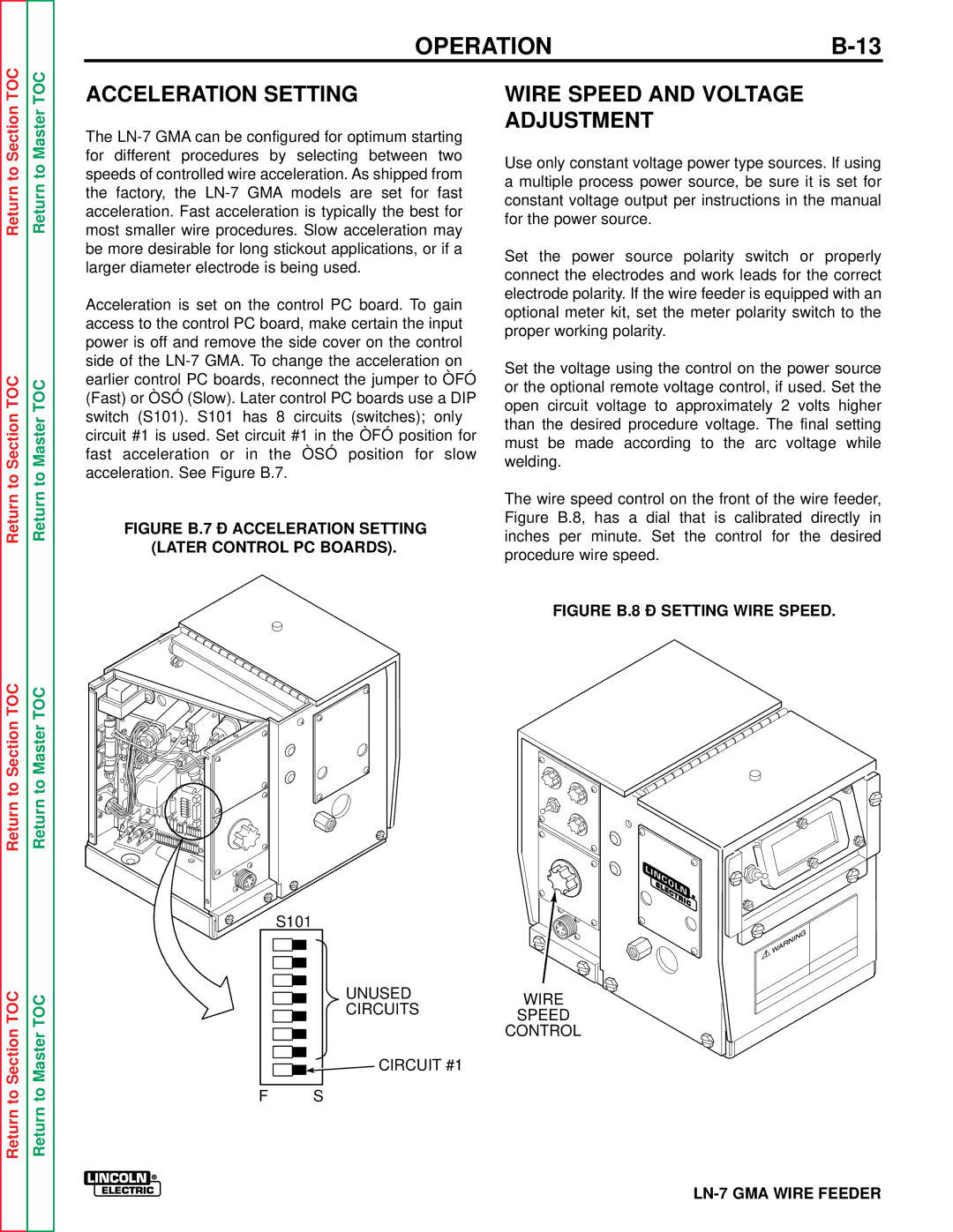
FIGURE B.7 – ACCELERATION SETTING
(LATER CONTROL PC BOARDS).
![]()
![]()
![]()
![]()
![]() S101
S101
UNUSED
CIRCUITS
CIRCUIT #1
F S
WIRE SPEED AND VOLTAGE ADJUSTMENT
Use only constant voltage power type sources. If using a multiple process power source, be sure it is set for constant voltage output per instructions in the manual for the power source.
Set the power source polarity switch or properly connect the electrodes and work leads for the correct electrode polarity. If the wire feeder is equipped with an optional meter kit, set the meter polarity switch to the proper working polarity.
Set the voltage using the control on the power source or the optional remote voltage control, if used. Set the open circuit voltage to approximately 2 volts higher than the desired procedure voltage. The final setting must be made according to the arc voltage while welding.
The wire speed control on the front of the wire feeder, Figure B.8, has a dial that is calibrated directly in inches per minute. Set the control for the desired procedure wire speed.
FIGURE B.8 – SETTING WIRE SPEED.
WIRE
SPEED