INSTALLATION |
Return to Section TOC
Return to Section TOC
Return to Section TOC
Return to Section TOC
Return to Master TOC
Return to Master TOC
Return to Master TOC
Return to Master TOC
1.For K291 and K404 cables, connect the end of the control cable with the lugged leads to the power source. If lead #21 is extended to work, do not connect leads to terminal #21 on terminal strip. Include any jumpers called for on the connection diagram. Do not add any other jumpers or connections.
WARNING
Never operate a Lincoln power source that has a jumper from #2 to #4 on the terminal strip, or a power source without a contactor, with this wire feeder. To do so would defeat the purpose of the grounding lead protector circuit and could result in the overheating of the electrical ground circuit to the wire feeder.
2.For constant voltage power sources with an output contactor but no terminal strip or
3.If input cables longer than the standard length must be used, K292 extension cables (50 ft/15.2 m) can be installed. These have polarized plugs on each end of the control cable and include a 4/0 (107 mm2) electrode cable. Install the extensions between the standard input cable and the wire feeder. Total input cable length should not exceed 400 ft (122 m). When using longer lengths of extension cables, it may be necessary to add parallel electrode cables to minimize the voltage drop in the cable.
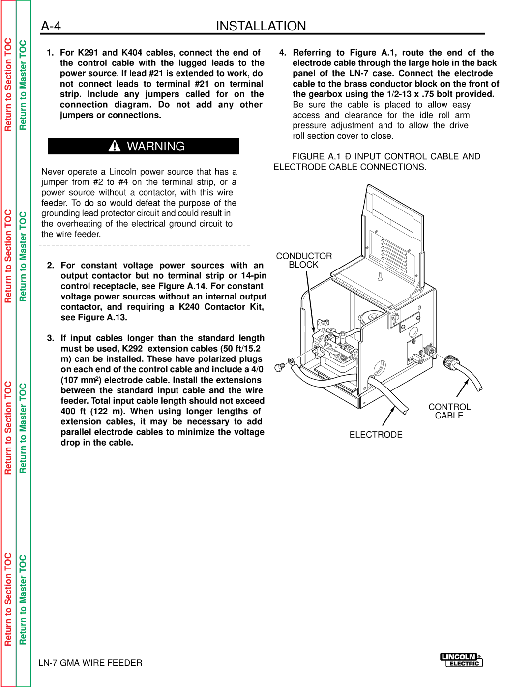
4.Referring to Figure A.1, route the end of the electrode cable through the large hole in the back panel of the
Be sure the cable is placed to allow easy access and clearance for the idle roll arm pressure adjustment and to allow the drive roll section cover to close.
FIGURE A.1 – INPUT CONTROL CABLE AND ELECTRODE CABLE CONNECTIONS.
CONDUCTOR
BLOCK
CONTROL
CABLE
ELECTRODE