to Section TOC
to Master TOC
TROUBLESHOOTING AND REPAIR |
SWING ARM ASSEMBLY REPLACEMENT FOR
FOUR-ROLL WIRE FEEDERS (continued)
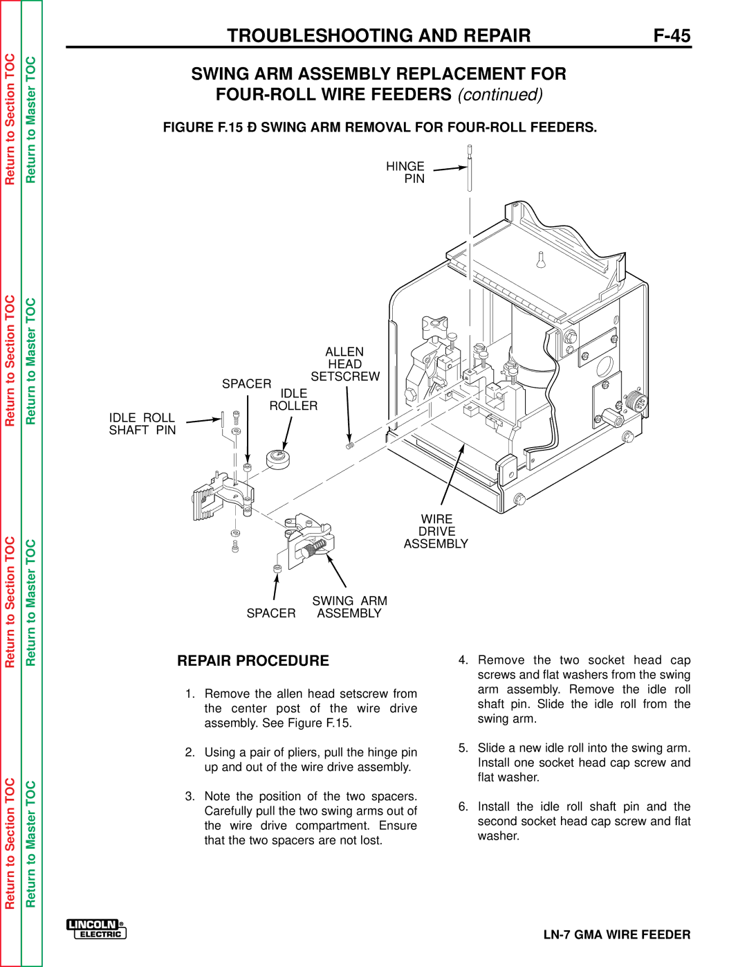
FIGURE F.15 – SWING ARM REMOVAL FOR FOUR-ROLL FEEDERS.
Return
to Section TOC
Return
to Master TOC
SPACER
HINGE
PIN
ALLEN
HEAD
SETSCREW
Return
Return to Section TOC
Return
Return to Master TOC
IDLE
ROLLER
IDLE ROLL
SHAFT PIN
WIRE
DRIVE
ASSEMBLY
SWING ARM
SPACER ASSEMBLY
Return to Section TOC
Return to Master TOC
REPAIR PROCEDURE
1.Remove the allen head setscrew from the center post of the wire drive assembly. See Figure F.15.
2.Using a pair of pliers, pull the hinge pin up and out of the wire drive assembly.
3.Note the position of the two spacers. Carefully pull the two swing arms out of the wire drive compartment. Ensure that the two spacers are not lost.
4.Remove the two socket head cap screws and flat washers from the swing arm assembly. Remove the idle roll shaft pin. Slide the idle roll from the swing arm.
5.Slide a new idle roll into the swing arm. Install one socket head cap screw and flat washer.
6.Install the idle roll shaft pin and the second socket head cap screw and flat washer.
