|
| THEORY OF OPERATION | |||||||||
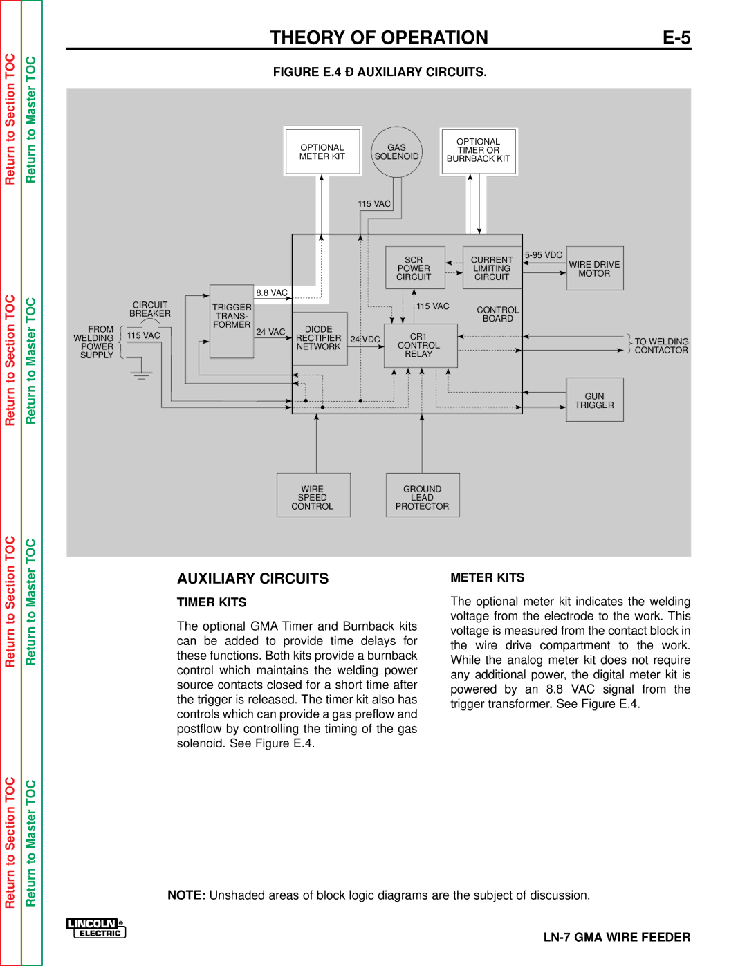
TOCSectionto | TOCMasterto | FIGURE E.4 – AUXILIARY CIRCUITS. |
| ||||||||
|
|
| |||||||||
|
|
|
|
|
|
|
|
|
|
|
|
Return | Return |
| OPTIONAL |
|
| GAS | OPTIONAL |
| |||
|
|
| TIMER OR |
| |||||||
|
|
| METER KIT |
|
| SOLENOID | BURNBACK KIT |
| |||
|
|
|
|
|
|
|
|
|
| ||
|
|
|
|
|
|
|
|
|
|
|
|
|
|
|
| 115 VAC |
|
|
|
|
| ||
|
|
|
|
|
|
|
|
|
|
|
|
|
|
|
|
|
|
|
|
|
|
|
|
|
|
|
|
|
|
|
|
|
|
|
|
|
|
|
|
|
|
|
| SCR | CURRENT | |
|
|
|
|
|
|
|
| WIRE DRIVE | ||
|
|
|
|
|
|
|
| POWER | LIMITING | |
|
|
|
|
|
|
|
| MOTOR | ||
|
|
|
|
|
|
|
| CIRCUIT | CIRCUIT | |
|
|
|
|
|
|
|
|
| ||
TOC | TOC |
|
|
| 8.8 VAC |
|
|
|
|
|
| CIRCUIT | TRIGGER |
|
|
| 115 VAC | CONTROL |
| ||
| BREAKER | TRANS- |
|
|
|
|
| |||
|
|
|
|
| BOARD |
| ||||
|
| FORMER |
|
|
|
|
| |||
FROM |
|
| DIODE |
|
|
|
| |||
to Section | to Master |
| 24 VAC |
|
|
|
| |||
115 VAC |
|
| CR1 |
|
| |||||
WELDING |
| RECTIFIER | 24 VDC |
|
| |||||
|
|
| TO WELDING | |||||||
POWER |
|
|
| NETWORK |
| CONTROL |
| |||
|
|
|
|
| CONTACTOR | |||||
SUPPLY |
|
|
|
|
| RELAY |
| |||
|
|
|
|
|
|
| ||||
|
|
|
|
|
|
|
|
| ||
Return | Return |
|
|
|
|
|
|
|
| GUN |
|
|
|
|
|
|
|
| TRIGGER | ||
|
|
|
|
|
|
|
|
| ||
|
|
|
|
|
| WIRE |
| GROUND |
|
|
|
|
|
|
|
| SPEED |
| LEAD |
|
|
|
|
|
|
|
| CONTROL |
| PROTECTOR |
|
|
TOC | TOC |
|
|
|
|
Section | Master |
|
| AUXILIARY CIRCUITS | METER KITS |
|
|
|
| ||
|
|
|
| TIMER KITS | The optional meter kit indicates the welding |
to | to |
|
| The optional GMA Timer and Burnback kits | voltage from the electrode to the work. This |
|
| voltage is measured from the contact block in | |||
Return | Return |
|
| ||
|
| these functions. Both kits provide a burnback | |||
|
| While the analog meter kit does not require | |||
|
|
|
| can be added to provide time delays for | the wire drive compartment to the work. |
|
|
|
|
| |
|
|
|
| control which maintains the welding power | any additional power, the digital meter kit is |
|
|
|
| source contacts closed for a short time after | |
|
|
|
| powered by an 8.8 VAC signal from the | |
|
|
|
| the trigger is released. The timer kit also has | |
|
|
|
| trigger transformer. See Figure E.4. | |
|
|
|
| controls which can provide a gas preflow and | |
|
|
|
|
| |
|
|
|
| postflow by controlling the timing of the gas |
|
|
|
|
| solenoid. See Figure E.4. |
|
to Section TOC | to Master TOC |
|
|
|
|
Return | Return |
|
| NOTE: Unshaded areas of block logic diagrams are the subject of discussion. | |
|
|
|
| ||
|
|
|
|
|
|
|
|
|
|
| |
|
|
|
|
| |
|
|
|
|
| |
|
|
|
|
| |