Return to Section TOC
Return to Section TOC
Return to Master TOC
Return to Master TOC
TROUBLESHOOTING AND REPAIR |
TRIGGER TRANSFORMER REPLACEMENT (continued)
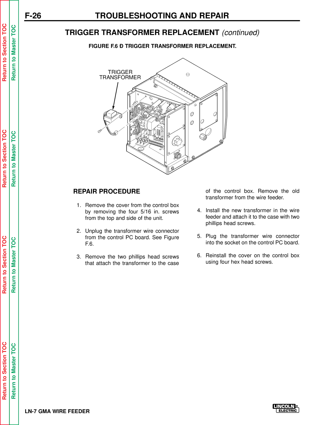
FIGURE F.6 – TRIGGER TRANSFORMER REPLACEMENT.
TRIGGER
TRANSFORMER
Return to Section TOC
Return to Section TOC
Return to Master TOC
Return to Master TOC
REPAIR PROCEDURE
1.Remove the cover from the control box by removing the four 5/16 in. screws from the top and side of the unit.
2.Unplug the transformer wire connector from the control PC board. See Figure F.6.
3.Remove the two phillips head screws that attach the transformer to the case
of the control box. Remove the old transformer from the wire feeder.
4.Install the new transformer in the wire feeder and attach it to the case with two phillips head screws.
5.Plug the transformer wire connector into the socket on the control PC board.
6.Reinstall the cover on the control box using four hex head screws.