Desktop or Shelf Installation:
When installing the Switch on the desktop or shelf, please attach the rubber feet to the Switch. Peel off the protective paper on the pads and attach them on the bottom of the Switch (one at each corner).
Rack Installation:
The 24 + 2 Giga SNMP Ethernet Switch is
Power On the Switch:
The 24 + 2 Giga SNMP Ethernet Switch has a universal power supply. The AC power cord connector is located at the rear of the unit and the On/Off switch is next to the connector. Connect the power cord from the power outlet to the Switch and push the On/Off Switch to “ON” position to power on the Switch. After the Switch is powered on, it will perform a
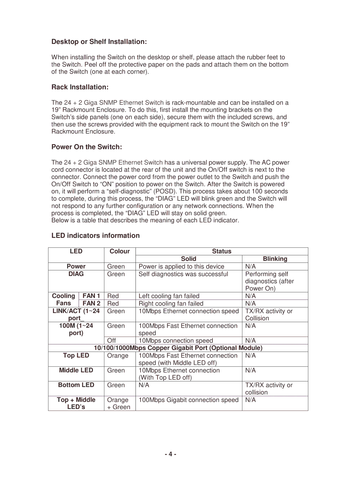
Below is a table that describes the meaning of each LED indicator.
LED indicators information
LED |
| Colour | Status |
| |
|
|
|
| Solid | Blinking |
Power | Green | Power is applied to this device | N/A | ||
DIAG | Green | Self diagnostics was successful | Performing self | ||
|
|
|
|
| diagnostics (after |
|
|
|
|
| Power On) |
Cooling |
| FAN 1 | Red | Left cooling fan failed | N/A |
Fans |
| FAN 2 | Red | Right cooling fan failed | N/A |
LINK/ACT | (1~24 | Green | 10Mbps Ethernet connection speed | TX/RX activity or | |
port_ |
|
| Collision | ||
100M (1~24 | Green | 100Mbps Fast Ethernet connection | N/A | ||
port) |
| speed |
| ||
|
|
| Off | 10Mbps connection speed | N/A |
|
|
| 10/100/1000Mbps | Copper Gigabit Port (Optional | Module) |
Top LED | Orange | 100Mbps Fast Ethernet connection | N/A | ||
|
|
|
| speed (with Middle LED off) |
|
Middle LED | Green | 10Mbps Ethernet connection | N/A | ||
|
|
|
| (With Top LED off) |
|
Bottom LED | Green | N/A | TX/RX activity or | ||
|
|
|
|
| collision |
Top + Middle | Orange | 100Mbps Gigabit connection speed | N/A | ||
LED’s | + Green |
|
| ||
- 4 -
