APPENDIX #4 – PIN CONFIGURATIONS FOR CONNECTION TO A COMPUTER
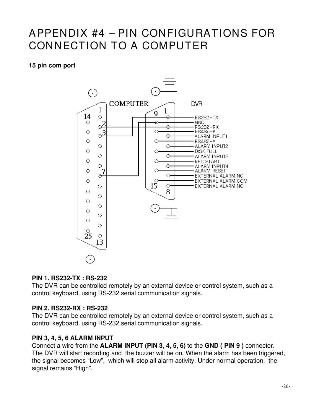
15 pin com port
‧‧
 DVR
DVR
‧
‧
PIN 1. RS232-TX : RS-232
The DVR can be controlled remotely by an external device or control system, such as a control keyboard, using
PIN 2. RS232-RX : RS-232
The DVR can be controlled remotely by an external device or control system, such as a control keyboard, using
PIN 3, 4, 5, 6 ALARM INPUT
Connect a wire from the ALARM INPUT (PIN 3, 4, 5, 6) to the GND ( PIN 9 ) connector. The DVR will start recording and the buzzer will be on. When the alarm has been triggered, the signal becomes “Low”, which will stop all alarm activity. Under normal operation, the signal remains “High”.