Testing Procedures
!WARNING
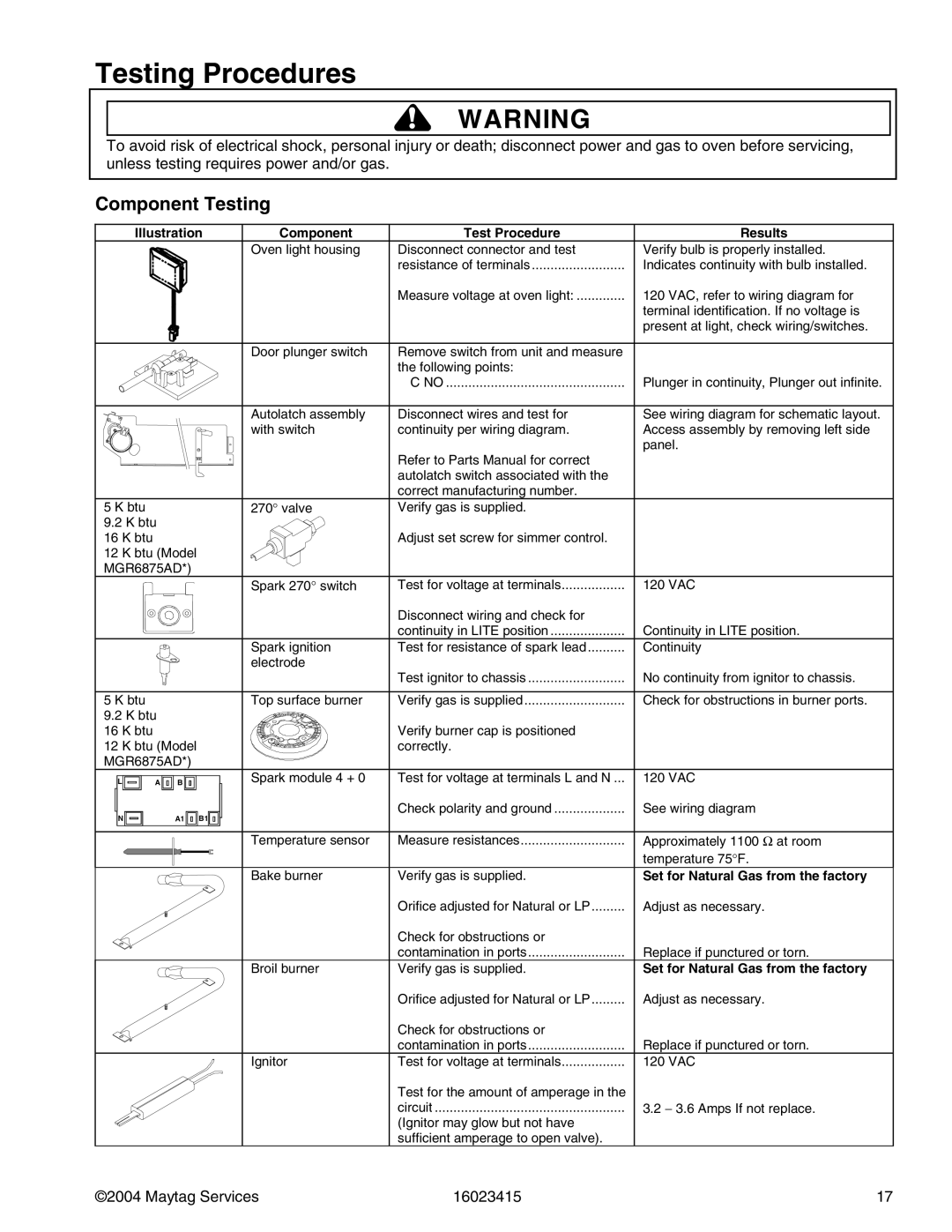
To avoid risk of electrical shock, personal injury or death; disconnect power and gas to oven before servicing, unless testing requires power and/or gas.
Component Testing
Illustration | Component | Test Procedure | Results | ||
|
|
| Oven light housing | Disconnect connector and test | Verify bulb is properly installed. |
|
|
|
| resistance of terminals | Indicates continuity with bulb installed. |
|
|
|
| Measure voltage at oven light: | 120 VAC, refer to wiring diagram for |
|
|
|
|
| terminal identification. If no voltage is |
|
|
|
|
| present at light, check wiring/switches. |
|
|
| Door plunger switch | Remove switch from unit and measure |
|
|
|
|
| the following points: |
|
|
|
|
| C NO | Plunger in continuity, Plunger out infinite. |
|
|
| Autolatch assembly | Disconnect wires and test for | See wiring diagram for schematic layout. |
|
|
| with switch | continuity per wiring diagram. | Access assembly by removing left side |
|
|
|
|
| panel. |
|
|
|
| Refer to Parts Manual for correct |
|
|
|
|
| autolatch switch associated with the |
|
|
|
|
| correct manufacturing number. |
|
5 K btu |
|
| 270° valve | Verify gas is supplied. |
|
9.2 K btu |
|
|
|
| |
16 K btu |
|
|
| Adjust set screw for simmer control. |
|
12 K btu (Model |
|
|
| ||
MGR6875AD*) |
|
|
| ||
|
|
| Spark 270° switch | Test for voltage at terminals | 120 VAC |
|
|
|
| Disconnect wiring and check for |
|
|
|
|
| continuity in LITE position | Continuity in LITE position. |
|
|
| Spark ignition | Test for resistance of spark lead | Continuity |
|
|
| electrode |
|
|
|
|
|
| Test ignitor to chassis | No continuity from ignitor to chassis. |
5 K btu |
|
| Top surface burner | Verify gas is supplied | Check for obstructions in burner ports. |
9.2 K btu |
|
|
|
| |
16 K btu |
|
|
| Verify burner cap is positioned |
|
12 K btu (Model |
| correctly. |
| ||
MGR6875AD*) |
|
|
| ||
L | A | B | Spark module 4 + 0 | Test for voltage at terminals L and N ... | 120 VAC |
N |
| A1 B1 |
| Check polarity and ground | See wiring diagram |
|
|
|
| ||
|
|
| Temperature sensor | Measure resistances | Approximately 1100 Ω at room |
|
|
|
|
| temperature 75°F. |
|
|
| Bake burner | Verify gas is supplied. | Set for Natural Gas from the factory |
|
|
|
| Orifice adjusted for Natural or LP | Adjust as necessary. |
|
|
|
| Check for obstructions or |
|
|
|
|
| contamination in ports | Replace if punctured or torn. |
|
|
| Broil burner | Verify gas is supplied. | Set for Natural Gas from the factory |
|
|
|
| Orifice adjusted for Natural or LP | Adjust as necessary. |
|
|
|
| Check for obstructions or |
|
|
|
|
| contamination in ports | Replace if punctured or torn. |
|
|
| Ignitor | Test for voltage at terminals | 120 VAC |
|
|
|
| Test for the amount of amperage in the |
|
|
|
|
| circuit | 3.2 − 3.6 Amps If not replace. |
|
|
|
| (Ignitor may glow but not have |
|
|
|
|
| sufficient amperage to open valve). |
|
©2004 Maytag Services | 16023415 | 17 |