Testing Procedures
!WARNING
To avoid risk of electrical shock, personal injury or death; disconnect power and gas to oven before servicing, unless testing requires power and/or gas.
Illustration/Component |
| Test Procedure |
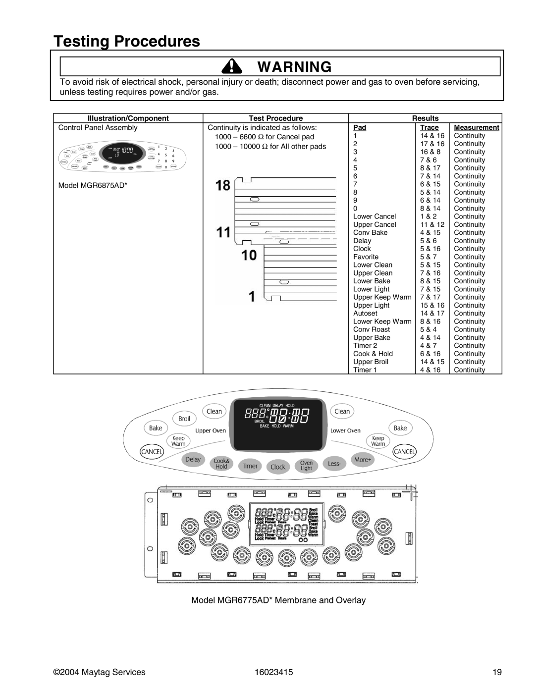
Control Panel Assembly | Continuity is indicated as follows: | |
| 1000 | – 6600 Ω for Cancel pad |
| 1000 | – 10000 Ω for All other pads |
Model MGR6875AD* |
|
|
Results
Pad | Trace | Measurement | ||
1 | 14 | & 16 | Continuity | |
2 | 17 | & 16 | Continuity | |
3 | 16 | & 8 | Continuity | |
4 | 7 | & 6 | Continuity | |
5 | 8 | & 17 | Continuity | |
6 | 7 | & 14 | Continuity | |
7 | 6 | & 15 | Continuity | |
8 | 5 | & 14 | Continuity | |
9 | 6 | & 14 | Continuity | |
0 | 8 | & 14 | Continuity | |
Lower Cancel | 1 | & 2 | Continuity | |
Upper Cancel | 11 | & 12 | Continuity | |
Conv Bake | 4 | & 15 | Continuity | |
Delay | 5 | & 6 | Continuity | |
Clock | 5 | & 16 | Continuity | |
Favorite | 5 | & 7 | Continuity | |
Lower Clean | 5 | & 15 | Continuity | |
Upper Clean | 7 | & 16 | Continuity | |
Lower Bake | 8 | & 15 | Continuity | |
Lower Light | 7 | & 15 | Continuity | |
Upper Keep Warm | 7 | & 17 | Continuity | |
Upper Light | 15 | & 16 | Continuity | |
Autoset | 14 | & 17 | Continuity | |
Lower Keep Warm | 8 | & 16 | Continuity | |
Conv Roast | 5 | & 4 | Continuity | |
Upper Bake | 4 | & 14 | Continuity | |
Timer 2 | 4 | & 7 | Continuity | |
Cook & Hold | 6 | & 16 | Continuity | |
Upper Broil | 14 | & 15 | Continuity | |
Timer 1 | 4 | & 16 | Continuity | |
Model MGR6775AD* Membrane and Overlay
©2004 Maytag Services | 16023415 | 19 |