1-Getting Started
7. The MaxNAS R8 interface components
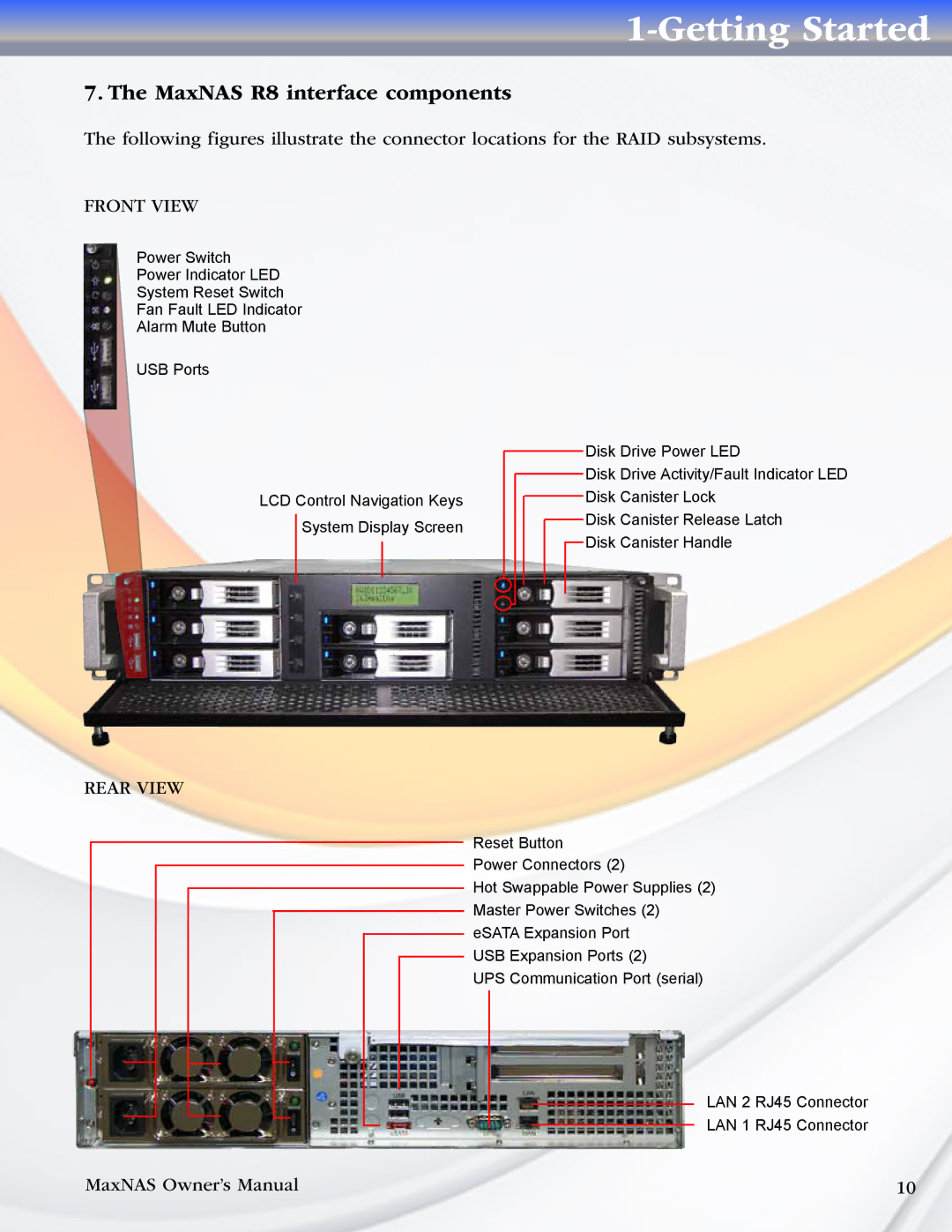
The following figures illustrate the connector locations for the RAID subsystems.
FRONT VIEW
Power Switch
Power Indicator LED
System Reset Switch
Fan Fault LED Indicator
Alarm Mute Button
USB Ports
LCD Control Navigation Keys
System Display Screen
Disk Drive Power LED
Disk Drive Activity/Fault Indicator LED
Disk Canister Lock
Disk Canister Release Latch
Disk Canister Handle
REAR VIEW
Reset Button
Power Connectors (2)
Hot Swappable Power Supplies (2)
Master Power Switches (2)
eSATA Expansion Port
USB Expansion Ports (2)
UPS Communication Port (serial)
LAN 2 RJ45 Connector
LAN 1 RJ45 Connector
MaxNAS Owner’s Manual | 10 |