Connecting an A/V Receiver or Stereo System or a Satellite Receiver or Other Device with
A/V Receiver or Stereo System
Figure 7
A digital audio cable and stereo audio cables are required. The digital audio cable is provided. The stereo audio cables are not included with the TV.
Satellite Receiver or Other Device with S-Video
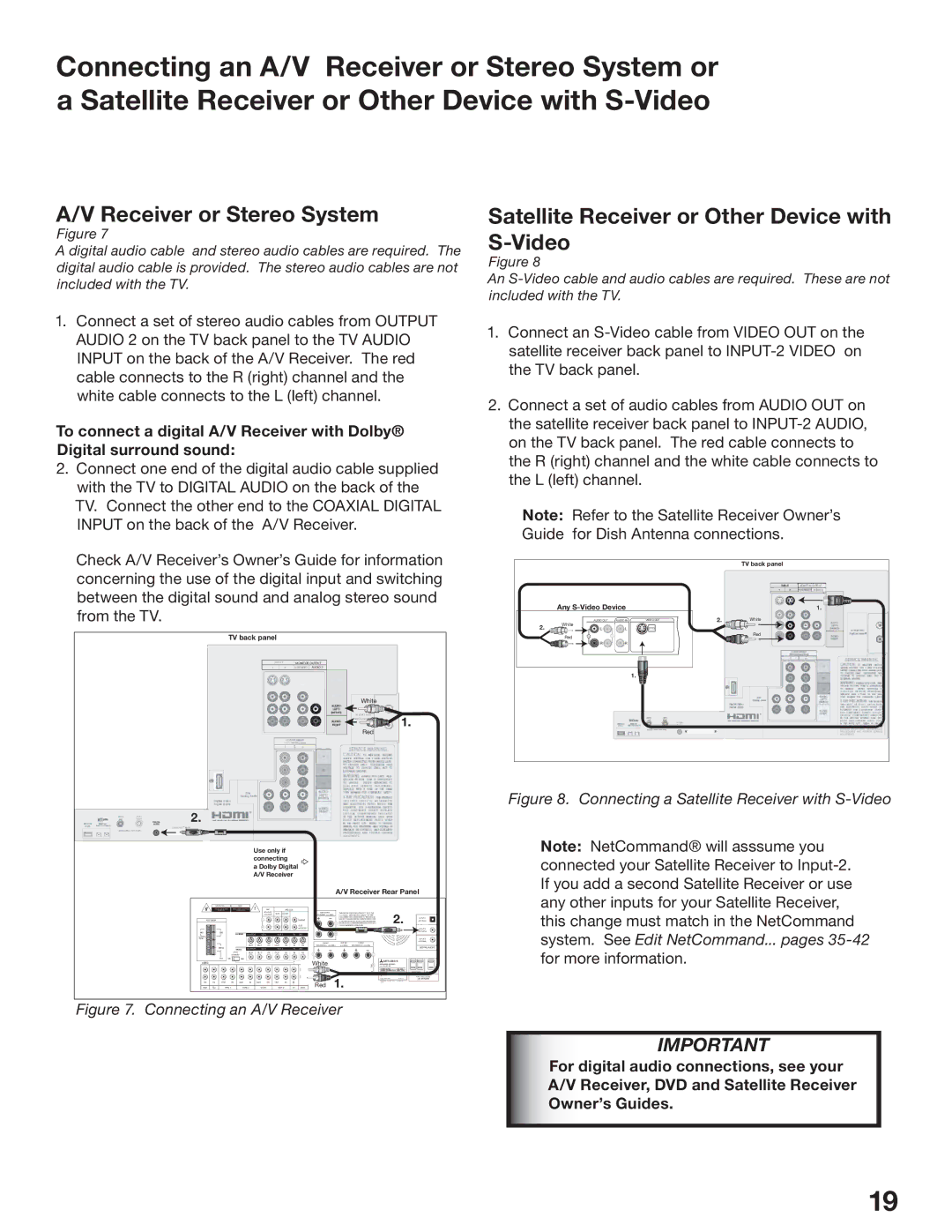
Figure 8
An
1.Connect a set of stereo audio cables from OUTPUT AUDIO 2 on the TV back panel to the TV AUDIO INPUT on the back of the A/V Receiver. The red cable connects to the R (right) channel and the white cable connects to the L (left) channel.
To connect a digital A/V Receiver with Dolby® Digital surround sound:
2.Connect one end of the digital audio cable supplied with the TV to DIGITAL AUDIO on the back of the TV. Connect the other end to the COAXIAL DIGITAL INPUT on the back of the A/V Receiver.
Check A/V Receiver’s Owner’s Guide for information concerning the use of the digital input and switching between the digital sound and analog stereo sound from the TV.
TV back panel
I N PUT |
| MONITOR OUTPUT |
1 | 2 | AUDIO/VIDEO 1 AUDIO 2 |
White
AUDIO-
LEFT/
(MONO)
I R EM ITTER
AUDIO- | N etCommand | 1. | |||
RIGHT |
|
|
|
|
|
Red
CO M
YPbPr (4
1
ANT 1
MAI N
DIGITAL | 2. |
AUDIO |
Cabl eCARD
LE /VH F/U H F)
ADJUSTMENTS.
Use only if connecting
a Dolby Digital A/V Receiver
|
|
|
|
|
|
|
|
|
|
|
|
|
|
|
|
|
|
| A/V Receiver Rear Panel |
| |||||||
|
| WARNING |
|
|
| AVIS |
| ! |
|
|
|
|
|
|
|
|
|
|
|
|
|
|
|
|
|
|
|
|
|
|
|
|
|
|
|
| REC |
| PRE OUT |
|
|
|
|
|
|
|
|
|
|
|
|
|
| ||
|
|
|
|
|
|
|
|
|
| SOURCE | SUR. | FRONT |
|
|
|
|
| SURROUND | THIS DEVICE COMPLIES WITH PART 15 OF THE | 2. |
|
| |||||
|
|
|
|
|
|
|
|
|
| LINE OUT |
|
|
|
|
| SPEAKERS | (6Ω MIN.) | FCC RULES. OPERATION IS SUBJECT TO THE |
|
| |||||||
|
|
|
|
|
|
|
|
|
|
|
|
|
|
|
|
|
|
|
| FOLLOWING TWO CONDITIONS: (1) THIS DEVICE | |||||||
ANTENNA |
|
|
|
|
|
|
| L |
|
|
| CENTER |
|
|
|
| MAY NOT CAUSE HARMFUL INTERFERENCE AND | ||||||||||
|
|
|
|
|
|
|
|
|
|
|
|
|
| (2) THIS DEVICE MUST ACCEPT ANY INTERFERENCE | (OPTICAL) | ||||||||||||
|
|
|
|
|
|
|
|
|
|
|
|
|
|
|
|
|
|
| L | RECEIVED, INCLUDING INTERFERENCE THAT MAY |
|
| |||||
|
|
|
|
|
|
|
|
|
| R |
|
|
| SUB |
|
|
|
| CAUSE UNDESIRED OPERATION. |
|
| ||||||
|
|
|
|
|
|
|
|
|
|
|
|
|
| WOOFER |
|
|
|
|
|
|
|
|
|
| |||
AM |
| 75Ω |
|
|
|
|
|
|
|
|
|
|
|
|
|
|
| R |
|
|
|
|
|
| (COAXIAL) | ||
|
|
|
|
| MONITOR | VCR 1 | VCR 2 | TV | DVD |
|
|
|
|
|
|
|
|
|
|
| |||||||
GND |
|
|
|
|
|
|
|
|
|
|
|
|
|
|
|
|
|
|
|
|
|
|
|
|
| ||
|
|
|
|
|
|
|
|
|
|
|
|
|
|
|
|
|
| FRONT | CENTER | FRONT |
|
| (COAXIAL) | ||||
|
|
|
|
|
|
| OUT | OUT | IN | OUT | IN | IN |
| IN |
|
| (6Ω MIN.) |
|
| DIGITAL AUDIO | |||||||
|
| 300Ω |
|
| VIDEO | MONITOR | VCR 1 | VCR 2 | TV | DVD |
|
|
|
|
|
|
|
|
|
| |||||||
|
|
|
|
| ATUO |
| OUT | OUT | IN | OUT | IN | IN |
| IN | L |
|
|
|
|
|
|
|
|
| |||
|
| FM |
| STANDBY |
|
|
|
|
|
|
|
|
|
|
|
|
| L |
|
|
|
| |||||
|
| ON |
| OFF |
|
|
|
|
|
|
|
|
| White |
|
|
|
|
|
|
|
| |||||
AUDIO |
|
|
|
|
|
|
|
|
|
|
|
| σ |
|
|
|
|
| R | MITSUBISHI |
|
| |||||
|
|
|
|
|
|
|
|
|
|
|
| τ |
|
|
|
|
|
|
| ||||||||
|
|
|
|
|
|
|
|
|
|
|
|
|
|
|
|
|
|
|
|
|
|
|
|
|
|
|
|
|
|
|
|
|
|
|
|
|
|
|
|
|
|
|
| L |
|
|
|
|
|
|
| SWITCHED | UNSWITCHED | ||
|
|
|
|
|
|
|
|
|
|
|
|
|
|
|
|
|
|
| 1. |
|
|
|
|
| AC OUTLETS | ||
IN | IN | OUT |
| IN | OUT | IN | OUT | IN | OUT | IN | IN |
| IN | R |
|
|
|
|
| ||||||||
AUX | CD | TAPE 1 | TAPE 2 | VCR 1 | VCR 2 | TV |
| DVD | Red |
|
|
|
|
|
|
| |||||||||||
Figure 7. Connecting an A/V Receiver
1.Connect an
2.Connect a set of audio cables from AUDIO OUT on the satellite receiver back panel to
Note: Refer to the Satellite Receiver Owner’s Guide for Dish Antenna connections.
|
|
|
|
|
|
|
|
|
|
|
| TV back panel |
|
|
| |||||
|
|
|
|
|
|
|
|
|
|
|
|
|
|
|
|
|
|
|
|
|
|
|
|
|
|
|
|
|
|
|
|
|
|
|
|
|
| INPUT |
|
|
|
|
|
|
|
|
|
|
|
|
|
|
|
| 1 | 2 |
|
| ||||
| Any |
|
|
|
|
|
|
|
|
| 1. |
| ||||||||
|
|
|
|
|
| AUDIO OUT |
| AUDIO IN |
| VIDEO OUT | 2. |
| White |
|
| DIO | ||||
2. | White | L |
| L |
| (Y/C) |
|
|
|
|
|
|
|
| ||||||
|
|
|
|
|
|
| 2 |
|
|
|
|
| Red |
|
|
| ||||
| Red | 1 |
|
|
|
|
|
|
|
| ||||||||||
|
|
|
|
|
| R |
| R |
|
|
|
|
|
|
|
|
|
|
|
|
|
|
|
|
|
|
|
|
|
|
|
|
|
|
|
|
|
|
|
|
|
1. ![]()
DIG ITAL
AU DIO
Cabl eCARD SLOT
M I N I M U M BR I G HT N E SS M EAS U R E M E NT
P R O C E D U R E S A N D P R OP E R S E RV I C E
ADJUSTMENTS
Figure 8. Connecting a Satellite Receiver with S-Video
Note: NetCommand® will asssume you connected your Satellite Receiver to
IMPORTANT
For digital audio connections, see your A/V Receiver, DVD and Satellite Receiver Owner’s Guides.
19