DCT3080 Installation Manual
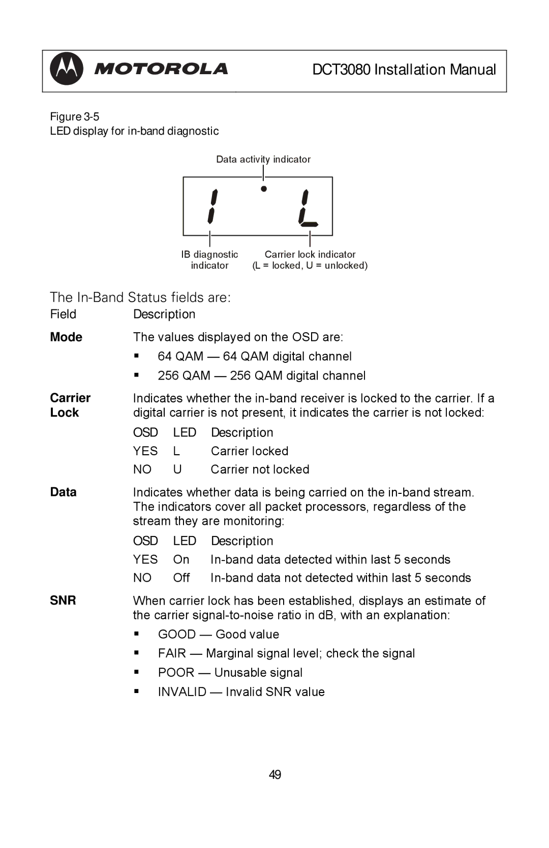
Figure
LED display for in-band diagnostic
Data activity indicator
|
|
| P | ||
|
|
| |||
| MUTE |
| MUTE |
|
|
|
| ||||
|
|
|
|
|
|
IB diagnostic |
| Carrier lock indicator | |||
indicator | (L = locked, U = unlocked) | ||||
The
Field Description
Mode | The values displayed on the OSD are: | ||
| 64 QAM — 64 QAM digital channel | ||
| 256 QAM — 256 QAM digital channel | ||
Carrier | Indicates whether the | ||
Lock | digital carrier is not present, it indicates the carrier is not locked: | ||
| OSD | LED | Description |
| YES | L | Carrier locked |
| NO | U | Carrier not locked |
Data | Indicates whether data is being carried on the | ||
| The indicators cover all packet processors, regardless of the | ||
| stream they are monitoring: | ||
| OSD | LED | Description |
| YES | On | |
| NO | Off | |
SNR | When carrier lock has been established, displays an estimate of | ||
| the carrier | ||
GOOD — Good value
FAIR — Marginal signal level; check the signal
POOR — Unusable signal
INVALID — Invalid SNR value
49