SECTION 2 | INSTALLATION |
|
|
8If necessary, seat an anchor in each hole. Use M5 x 38 mm
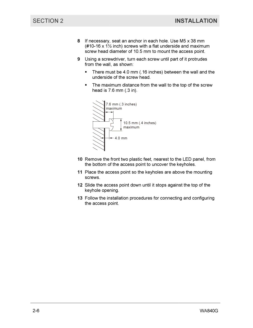
9Using a screwdriver, turn each screw until part of it protrudes from the wall, as shown:
!There must be 4.0 mm (.16 inches) between the wall and the underside of the screw head.
!The maximum distance from the wall to the top of the screw head is 7.6 mm (.3 in).
7.6mm (.3 inches) maximum
10.5mm (.4 inches) maximum
![]()
![]()
![]() 4.0 mm
4.0 mm
10Remove the front two plastic feet, nearest to the LED panel, from the bottom of the access point to uncover the keyholes.
11Place the access point so the keyholes are above the mounting screws.
12Slide the access point down until it stops against the top of the keyhole opening.
13Follow the installation procedures for connecting and configuring the access point.
WA840G |