Chapter 2 - Installation
2.6Modem LED Indicators
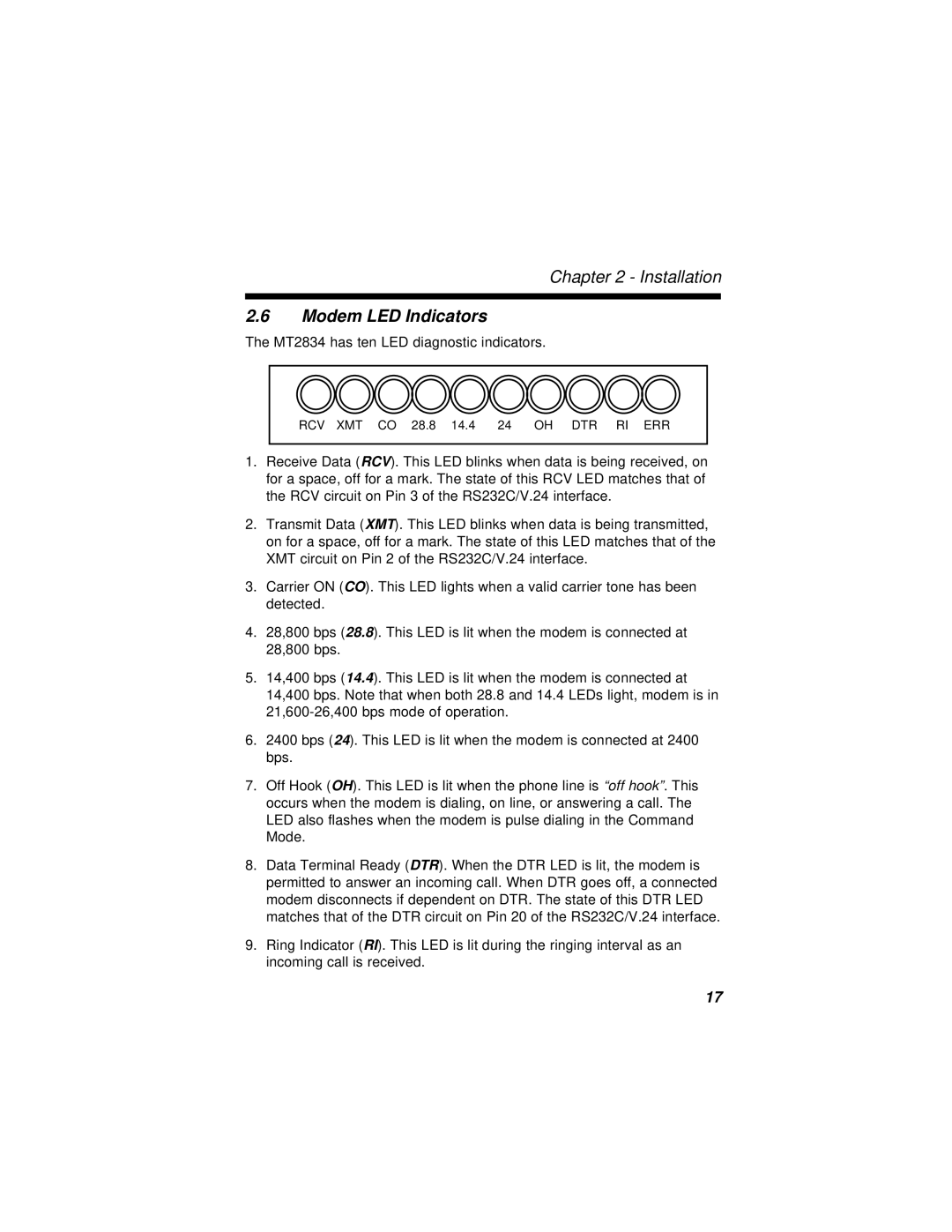
The MT2834 has ten LED diagnostic indicators.
RCV XMT CO 28.8 14.4 24 OH DTR RI ERR
1.Receive Data (RCV). This LED blinks when data is being received, on for a space, off for a mark. The state of this RCV LED matches that of the RCV circuit on Pin 3 of the RS232C/V.24 interface.
2.Transmit Data (XMT). This LED blinks when data is being transmitted, on for a space, off for a mark. The state of this LED matches that of the XMT circuit on Pin 2 of the RS232C/V.24 interface.
3.Carrier ON (CO). This LED lights when a valid carrier tone has been detected.
4.28,800 bps (28.8). This LED is lit when the modem is connected at 28,800 bps.
5.14,400 bps (14.4). This LED is lit when the modem is connected at 14,400 bps. Note that when both 28.8 and 14.4 LEDs light, modem is in
6.2400 bps (24). This LED is lit when the modem is connected at 2400 bps.
7.Off Hook (OH). This LED is lit when the phone line is “off hook”. This occurs when the modem is dialing, on line, or answering a call. The LED also flashes when the modem is pulse dialing in the Command Mode.
8.Data Terminal Ready (DTR). When the DTR LED is lit, the modem is permitted to answer an incoming call. When DTR goes off, a connected modem disconnects if dependent on DTR. The state of this DTR LED matches that of the DTR circuit on Pin 20 of the RS232C/V.24 interface.
9.Ring Indicator (RI). This LED is lit during the ringing interval as an incoming call is received.
17