Receiver/Gateway
Computer Interface Manual
Conettix D6600/D6100
Trademarks
Bosch Security Systems, Inc. | 1/07 |
Contents
Bosch Security Systems, Inc. | 1/07 |
Bosch Security Systems, Inc. | 1/07 |
Figures
Tables
Bosch Security Systems, Inc. | 1/07 |
Bosch Security Systems, Inc. | 1/07 |
1.0System Connection
1.1Conettix D6680 Ethernet Network
Adapter Connection
1.2Direct Connection – RS-232
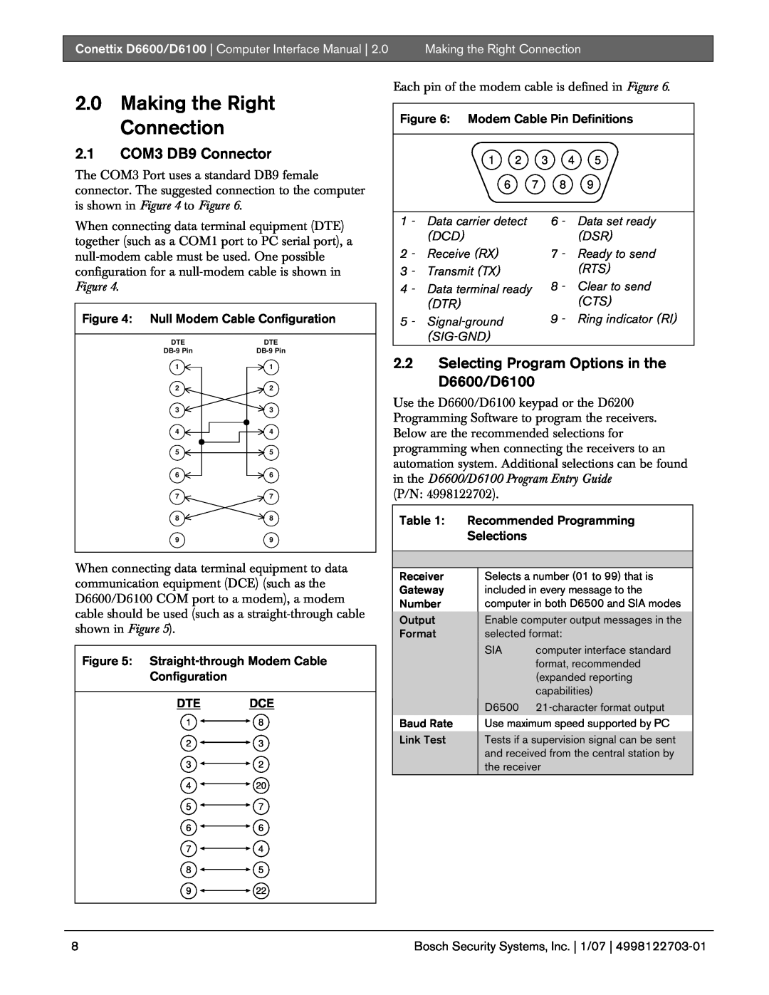
2.1COM3 DB9 Connector
5 - Signal-ground SIG-GND
8 - Clear to send CTS 9 - Ring indicator RI
2.0Making the Right Connection
3.0Computer Communication Protocols
3.1D6500 Mode Messages
Computer Communication Protocols
3.1.1Acron Super Fast Message Type
3.1.2Ademco 4-1Express Message Type b
h b r r l s s s s s s a a a a s E s s s X t
3.1.3Ademco 4-2Express Message Type c
h c r r l s s s s s s a a a a s E s s X Y t
3.1.4Ademco Contact-IDMessage Type a
h a r r l s a a a a 1 8 Q X Y Z G G C C C t
3.1.5Ademco High Speed, 4-8-1Message Type f
h f r r l a a a a a a s C C C C s C C C C s C t
3.1.6ADT SIA Message Type S
ADT SIA Message Type S Byte Description
3.1.7Caller ID Message Type e
Computer Communication Protocols
3.1.8CFSK Message Type
h i r r l s s s s a a a a a a T T E E s s t
Table 10: CFSK Message Type i Byte Description
3.1.9Common Formats Message Type
3.1.10 DNIS/ANI Message Type N
3.1.11 DSC 4-3Message Type d
Table 13: DSC-4-3Message Type d Byte Description
Bosch Security Systems, Inc. | 1/07 |
3.1.12 FBI Super Fast Message Type F
h F r r l s s s s s s a a a a T Z Z E s s t
3.1.13 ITI Message Type
h I r r l s s s a T a a a a G I Z Z E W N t
3.1.15 Robofon Message Type j
h j r r l s s s s a a a a a a E E s s s s t
Table 17: Robofon Message Type j Byte Description
Computer Communication Protocols
Bosch Security Systems, Inc. | 1/07 |
3.1.16 Sescoa Super Speed Message Type
Computer Communication Protocols
Bosch Security Systems, Inc. | 1/07 |
Computer Communication Protocols
Bosch Security Systems, Inc. | 1/07 |
3.1.19 Seriee FSK Message Type k
h k r r l s s s s s s a a a a a s E s Z Z t
3.1.20 Seriee DTMF Message Type l
h l r r l L L * a a a a a a
3.1.21 SIA Message Type S
Defined Messages
Table 23 SIA Message Type S Byte Description
Undefined Messages
3.1.22 Silent Knight FSK0 Message Type
h 1 r r l s s s s s s a a a a s E s s s Z t
Optional Silent Knight SK1 Message Type m
Computer Communication Protocols
Bosch Security Systems, Inc. | 1/07 |
Table 27 Silent Knight Automation Format
Computer Communication Protocols
3.1.23 Silent Knight FSK2 Message Type m
h m r r l s a a a a a a a a “ E E Z Z “
h E r r l s s s s s s A A A A s A s s X Y t
Computer Communication Protocols
3.1.25 Telim Message Type n
Table 30: Telim Message Type n Byte Description
3.1.26 Text Message Message Type
h 3 r r l P R I N T E R
3.1.27 Varitech FSK 4-1Message Type
h 1 r r l s s s s s s a a a a s E s s s X t
Varitech FSK 4-1Message Type 1 Byte Description
3.1.28 Varitech FSK 4-2Message Type
3.1.29 VONK Message Type
Table 34 VONK Message Type V Byte Description
3.1.30 X-SIAText Message Type S
h S r r l # a a a a | E M M Z Z Z Z * ` T
3.2SIA Mode Messages
Computer Communication Protocols
3.2.2Ademco Contact-IDMessage Type a
Figure 8: Message sent to printer
mm/ddshh:mmsLxxsCIDsACCTsaaaa+++sACCsa
aaasNNNsEVENT=XYZsG=GGsC=CCC
3.2.3Ademco 4-1Express Message Type b
Figure 9: Message sent to printer
mm/ddshh:mmsLxxsE41sACCTsaaaasEVENT=X
Table 42: Ademco 4-1Express Message
3.2.4Ademco 4-2Express Message Type c
Figure 10: Message sent to printer
mm/ddshh:mmsLxxsE42sACCTsaaaasEVENT=XY
Table 44 Ademco 4-2Express Message
SCANCOM 5-8-1, 6-8-1- available upon request
Figure 11: Message sent to printer
Table 46: Ademco High Speed, 4-8-1Message
Type f Printer Output
3.2.6ADT SIA Message Type <TAB>
3.2.7Caller ID Message Type <TAB>
Computer Communication Protocols
Bosch Security Systems, Inc. 1/07
3.2.8CFSK Message Type
Table 49: CFSK Message Type I Byte Description
3.2.9Common Formats Message Type TAB
Figure 12: Message sent to printer
Figure 13: Message sent to printer
MM/DDsHH:MMsLxxSIA +++TEXT +++TEXT
3.2.10 DNIS/ANI Message Type N
Figure 14: Message sent to printer
3.2.11 DSC 4-3Message Type d
Computer Communication Protocols
3.2.12 FBI Super Fast Message Type F
Computer Communication Protocols
3.2.13 ITI Message Type
Table 61: ITI Message Type I Byte Description
3.2.14 Link Test Message Type <TAB>
Computer Communication Protocols
3.2.15 RB2000 Message Type R Description
Table 63 RB2000 Message Type R Byte Description
Figure 17 Single message sent to Printer
MM/DD HH:MM Lxx RB2 ACCT
3.2.16 Robofon Message Type j
Table 65: Robofon Message Type j Byte Description
Computer Communication Protocols
Bosch Security Systems, Inc. | 1/07 |
Figure 19: Message sent to printer
Computer Communication Protocols
3.2.19 Seriee DTMF Message Type l
3.2.20 Seriee FSK Message Type k
Computer Communication Protocols
Bosch Security Systems, Inc. | 1/07 |
3.2.21 Sescoa Super Speed Message Type
Figure 21: Message sent to printer
mm/ddshh:mmsLxxSESsACCTsaaaa
+++sACCsaaaasEEEseeeeeeeeeeeeee
3.2.22 Silent Knight FSK Message Type <TAB>
3.2.23 Silent Knight FSK1 Message Type m
Computer Communication Protocols
Bosch Security Systems, Inc. | 1/07 |
Optional Silent Knight FSK1 Message Type m
Table 77: Silent Knight FSK1 Optional Outputs
Computer Communication Protocols
Bosch Security Systems, Inc. 1/07
3.2.24 Silent Knight FSK2 Message Type m
Computer Communication Protocols
Bosch Security Systems, Inc. | 1/07 |
EEZZ”EEZZ”EEZZ”EEZZ”
3.2.25 Silent Knight FSK80 Message Type E
Figure 22: Message sent to printer
Table 80: Silent Knight FSK80 Printer/LCD output
Computer Communication Protocols
3.2.26 Telim Message Type n
Table 81 Telim Message Type n Byte Description
3.2.27 Varitech FSK 4-1Message Type <TAB>
Computer Communication Protocols
3.2.28 Varitech FSK 4-2Message Type <TAB>
3.2.29 VONK Message Type
Table 84: VONK Message Type V Byte Description
Computer Communication Protocols
3.2.30 X-SIAtext Message Type <TAB>
Figure 23: Message sent to printer
MM/DDsHH MMsLxxsSIAsACCTsAAAA+++sEMMZZ
ZZ*TTTTTTTTTTTTTNM+++sEMMZZZZ*TTTTT TTTTTTTTNM
3.2.31 SafeCom Message Type p
Table 87: SafeCom Message Type p Byte Description
Computer Communication Protocols
Bosch Security Systems, Inc. | 1/07 |
3.3Input Command Processing
Table 89: Input Command Output Messages
Table 88: ASCII Text Message to Automation
Port
2 - Event Qualifier - E = New Event, R = Restore
5 - Zone ID number* - reporting the alarm 001 to
Appendix A Contact ID Event Code Classifications
Figure 24: Contact ID format
Bosch Security Systems, Inc. | 1/07 |
Bosch Security Systems, Inc. 1/07
Bosch Security Systems, Inc. | 1/07 |
Bosch Security Systems, Inc. | 1/07 |
Bosch Security Systems, Inc. | 1/07 |
Appendix B: Internal Messages
Table 91: Internal Messages
Table 91: Internal Messages continued
Bosch Security Systems, Inc. | 1/07 |
Table 91: Internal Messages continued
Bosch Security Systems, Inc. 1/07
Appendix C Modem IIIa2 Messages
Table 92 Modem IIIa2 Messages
Bosch Security Systems, Inc. | 1/07 |
C.1 Zonex and
Table 92: Modem IIIa2 Messages continued
Bosch Security Systems, Inc. | 1/07 |
C.1 Zonex and
Comex
Table 92 Modem IIIa2 Messages continued
Bosch Security Systems, Inc. | 1/07 |
C.1 Zonex and
Comex
Table 92: Modem IIIa2 Messages continued
Bosch Security Systems, Inc. | 1/07 |
C.1 Zonex and
Comex
Table 92: Modem IIIa2 Messages continued
Bosch Security Systems, Inc. | 1/07 |
C.1 Zonex and
Comex
Table 92 Modem IIIa2 Messages continued
Bosch Security Systems, Inc. | 1/07 |
C.1 Zonex and
Comex
Table 92: Modem IIIa2 Messages continued
Bosch Security Systems, Inc. | 1/07 |
C.1 Zonex and
Comex
Table 92: Modem IIIa2 Messages continued
Bosch Security Systems, Inc. 1/07
C.1 Zonex and
Comex
Table 92: Modem IIIa2 Messages continued
Bosch Security Systems, Inc. | 1/07 |
C.1 Zonex and
Comex
Table 92 Modem IIIa2 Messages continued
Bosch Security Systems, Inc. | 1/07 |
C.1 Zonex and
Comex
Table 92: Modem IIIa2 Messages continued
Bosch Security Systems, Inc. | 1/07 |
C.1 Zonex and
Comex
Table 92: Modem IIIa2 Messages continued
Bosch Security Systems, Inc. | 1/07 |
C.1 Zonex and
Comex
Table 92: Modem IIIa2 Messages continued
Bosch Security Systems, Inc. | 1/07 |
C.1 Zonex and
Comex
Table 92: Modem IIIa2 Messages continued
Bosch Security Systems, Inc. | 1/07 |
C.1 Zonex and
Comex
Table 92: Modem IIIa2 Messages continued
Bosch Security Systems, Inc. | 1/07 |
C.1 Zonex and
Comex
Table 92: Modem IIIa2 Messages continued
Bosch Security Systems, Inc. | 1/07 |
C.1 Zonex and
Comex
Table 92: Modem IIIa2 Messages continued
Bosch Security Systems, Inc. | 1/07 |
C.1 Zonex and
Comex
Table 92: Modem IIIa2 Messages continued
Bosch Security Systems, Inc. | 1/07 |
C.1 Zonex and
Comex
Table 92: Modem IIIa2 Messages continued
Bosch Security Systems, Inc. 1/07
C.1 Zonex and
Comex
Table 92 Modem IIIa2 Messages continued
Bosch Security Systems, Inc. | 1/07 |
C.1 Zonex and
Comex
Table 92: Modem IIIa2 Messages continued
Bosch Security Systems, Inc. | 1/07 |
C.1 Zonex and
Comex
Table 92: Modem IIIa2 Messages continued
Bosch Security Systems, Inc. | 1/07 |
C.1 Zonex and
Comex
Table 92: Modem IIIa2 Messages continued
Bosch Security Systems, Inc. 1/07
C.1 Zonex and
Comex
Table 92: Modem IIIa2 Messages continued
Bosch Security Systems, Inc. | 1/07 |
C.1 Zonex and
Comex
Table 92: Modem IIIa2 Messages continued
Bosch Security Systems, Inc. 1/07
C.1 Zonex and
Comex
Table 92: Modem IIIa2 Messages continued
Bosch Security Systems, Inc. | 1/07 |
C.1 Zonex and
Comex
Table 92: Modem IIIa2 Messages continued
Bosch Security Systems, Inc. | 1/07 |
C.1 Zonex and
Comex
Table 92: Modem IIIa2 Messages continued
Bosch Security Systems, Inc. | 1/07 |
C.1 Zonex and
Comex
Table 92: Modem IIIa2 Messages continued
Bosch Security Systems, Inc. | 1/07 |
C.1 Zonex and
Comex
Table 92: Modem IIIa2 Messages continued
Bosch Security Systems, Inc. | 1/07 |
C.1 Zonex and
Comex
Table 92: Modem IIIa2 Messages continued
Bosch Security Systems, Inc. | 1/07 |
C.1 Zonex and
Comex
Table 92: Modem IIIa2 Messages continued
Bosch Security Systems, Inc. | 1/07 |
C.1 Zonex and
Comex
Table 92: Modem IIIa2 Messages continued
Bosch Security Systems, Inc. | 1/07 |
C.1 Zonex and
Comex
Table 92: Modem IIIa2 Messages continued
Bosch Security Systems, Inc. | 1/07 |
C.1 Zonex and
Comex
Table 92: Modem IIIa2 Messages continued
Bosch Security Systems, Inc. | 1/07 |
C.1 Zonex and
Comex
Table 92: Modem IIIa2 Messages continued
Bosch Security Systems, Inc. | 1/07 |
C.1 Zonex and
Comex
Table 92: Modem IIIa2 Messages continued
Bosch Security Systems, Inc. | 1/07 |
C.1 Zonex and
Comex
Table 92: Modem IIIa2 Messages continued
Bosch Security Systems, Inc. | 1/07 |
C.1 Zonex and
Comex
Table 92: Modem IIIa2 Messages continued
Bosch Security Systems, Inc. | 1/07 |
C.1 Zonex and
Comex
Table 92 Modem IIIa2 Messages continued
Bosch Security Systems, Inc. | 1/07 |
C.1 Zonex and
Comex
Table 92: Modem IIIa2 Messages continued
Bosch Security Systems, Inc. | 1/07 |
C.1 Zonex and
Comex
Table 92: Modem IIIa2 Messages continued
Bosch Security Systems, Inc. | 1/07 |
C.1 Zonex and
Comex
Table 92: Modem IIIa2 Messages continued
Bosch Security Systems, Inc. | 1/07 |
C.1 Zonex and
Comex
Table 92: Modem IIIa2 Messages continued
Bosch Security Systems, Inc. | 1/07 |
C.1 Zonex and
Comex
Table 92: Modem IIIa2 Messages continued
Bosch Security Systems, Inc. 1/07
C.1 Zonex and
Comex
Table 92: Modem IIIa2 Messages continued
Bosch Security Systems, Inc. 1/07
C.1 Zonex and
Comex
Table 92: Modem IIIa2 Messages continued
Bosch Security Systems, Inc. | 1/07 |
C.1 Zonex and
Comex
Table 92: Modem IIIa2 Messages continued
Bosch Security Systems, Inc. 1/07
C.1 Zonex and
Comex
Table 92: Modem IIIa2 Messages continued
Bosch Security Systems, Inc. | 1/07 |
C.1 Zonex and
Comex
Table 92 Modem IIIa2 Messages continued
Bosch Security Systems, Inc. | 1/07 |
C.1 Zonex and
Comex
Table 92: Modem IIIa2 Messages continued
Bosch Security Systems, Inc. 1/07
C.1 Zonex and
Comex
Table 92: Modem IIIa2 Messages continued
Bosch Security Systems, Inc. | 1/07 |
C.1 Zonex and
Comex
Table 92: Modem IIIa2 Messages continued
Bosch Security Systems, Inc. | 1/07 |
C.1 Zonex and
Comex
Table 92: Modem IIIa2 Messages continued
Bosch Security Systems, Inc. | 1/07 |
C.1 Zonex and
Comex
Table 92: Modem IIIa2 Messages continued
Bosch Security Systems, Inc. | 1/07 |
C.1 Zonex and
Comex
Table 92: Modem IIIa2 Messages continued
Bosch Security Systems, Inc. | 1/07 |
C.1 Zonex and
Comex
Table 92: Modem IIIa2 Messages continued
Bosch Security Systems, Inc. | 1/07 |
C.1 Zonex and
Comex
Table 92: Modem IIIa2 Messages continued
Bosch Security Systems, Inc. 1/07
C.1 Zonex and
Comex
Table 92: Modem IIIa2 Messages continued
Bosch Security Systems, Inc. | 1/07 |
C.1 Zonex and
Comex
Table 92: Modem IIIa2 Messages continued
Bosch Security Systems, Inc. | 1/07 |
C.1 Zonex and
Comex
Table 92: Modem IIIa2 Messages continued
Bosch Security Systems, Inc. | 1/07 |
C.1 Zonex and
Comex
Table 92: Modem IIIa2 Messages continued
Bosch Security Systems, Inc. | 1/07 |
C.1 Zonex and
Comex
Table 92 Modem IIIa2 Messages continued
Bosch Security Systems, Inc. | 1/07 |
Event
Device/Mode
Table 92: Modem IIIa2 Messages continued
Bosch Security Systems, Inc. | 1/07 |
Table 92: Modem IIIa2 Messages continued
Bosch Security Systems, Inc. | 1/07 |
point Point Code
Digit One =4
Table 92: Modem IIIa2 Messages continued
Bosch Security Systems, Inc. | 1/07 |
Table 92 Modem IIIa2 Messages continued
Bosch Security Systems, Inc. 1/07
Table 92: Modem IIIa2 Messages continued
Bosch Security Systems, Inc. | 1/07 |
C.1 Zonex and
Comex
Table 92 Modem IIIa2 Messages continued
Bosch Security Systems, Inc. | 1/07 |
C.1 Zonex and
Comex
Table 92: Modem IIIa2 Messages continued
Bosch Security Systems, Inc. | 1/07 |
C.1 Zonex and
Comex
C.1 Zonex and Comex Translation
Table 93 Point to Zonex Translation
Table 94: User ID to Comex Translation
Example 1: Log Threshold Since Last Call
Bosch Security Systems, Inc. | 1/07 |
Appendix D Network Messages D6600 Only
Table 96: Network Messages
Table 96: Network Messages continued
Bosch Security Systems, Inc. | 1/07 |
Condition 008 =
Attack
Table 96: Network Messages continued
Bosch Security Systems, Inc. | 1/07 |
Bosch Security Systems, Inc. | 1/07 |
Appendix E: Pulse Output
Table 97: Pulse 3/1 Format
Bosch Security Systems, Inc. | 1/07 |
Bosch Security Systems, Inc. | 1/07 |
Table 100: Pulse 3/2
Table 101: Pulse 4/1
Bosch Security Systems, Inc. 1/07
Table 102 Pulse 4/1E Menu 3.1.3.3 4/1 Extended =
Table 103: Pulse 4/1E Menu 3.1.3.3 4/1 Extended =
Bosch Security Systems, Inc. | 1/07 |
Table 104: Pulse 4/2
Table 105: Pulse 4/3
h 9 r r l s s s s a a a a C C C C C C C C t
Table 106: Generic Byte Description
Table 107: Generic SIA Byte Description
Bosch Security Systems, Inc. | 1/07 |
Table 108: Message Examples
Bosch Security Systems, Inc. 1/07
Communication
Mode
Table 108: Message Examples continued
Bosch Security Systems, Inc. | 1/07 |
Bosch Security Systems, Inc. 1/07
Appendix G: ADT SIA Report Codes
Table 109: ADT SIA Report Codes
Table 109: ADT SIA Report Codes Continued
Bosch Security Systems, Inc. | 1/07 |
Bosch Security Systems, Inc. | 1/07 |
Appendix H: D6600 RB2000 Messages
Table 110: D6600 RB2000 Messages
Table 110: D6600 RB2000 Messages continued
Bosch Security Systems, Inc. | 1/07 |
Table 110: D6600 RB2000 Messages continued
Bosch Security Systems, Inc. | 1/07 |
Table 110: D6600 RB2000 Messages continued
Bosch Security Systems, Inc. | 1/07 |
Table 110: D6600 RB2000 Messages continued
Bosch Security Systems, Inc. | 1/07 |
Table 110 D6600 RB2000 Messages continued
Bosch Security Systems, Inc. 1/07
Table 110: D6600 RB2000 Messages continued
Bosch Security Systems, Inc. | 1/07 |
D6600 SafeCom Messages
Appendix I: D6600 SafeCom Messages
Appendix
Bosch Security Systems, Inc. | 1/07 |
Appendix
D6600 SafeCom Messages
Bosch Security Systems, Inc. | 1/07 |
Appendix
D6600 SafeCom Messages
Bosch Security Systems, Inc. | 1/07 |
Appendix
D6600 SafeCom Messages
Bosch Security Systems, Inc. | 1/07 |
Appendix
D6600 SafeCom Messages
Bosch Security Systems, Inc. | 1/07 |
Appendix
D6600 SafeCom Messages
Appendix
D6600 SafeCom Messages
Bosch Security Systems, Inc. 1/07
Character Meaning
Table 115: Explanation of Printer Output Items
Appendix
D6600 SafeCom Messages
Bosch Security Systems, Inc. 1/07
Modem IIe Format
Table 116: Supported Event Codes
Appendix
D6600 SafeCom Messages
Appendix
D6600 SafeCom Messages
Table 116: Supported Event Codes
Bosch Security Systems, Inc. 1/07
Fairport, NY Customer Service: 800
Bosch Security Systems, Inc 130 Perinton Parkway
Technical Support: 888
2007 Bosch Security Systems, Inc 4998122703-01