Chapter 2 - Installation
9.Set both local and remote modems to either Normal (&E0&W0) mode or to Reliable (&E2&W0) mode.
10.Verify leased line transmit level (DIP-Switch #3) setting (Section 2.3.1).
11.Proceed to Chapter 3 of this manual, or to your data communications software manual.
*All Multi-Tech rack-mounted modem cards (except MT1432/2834) are interchangeable among all types of modem racks. There is, however, slight LED differences. Model #CC216G is a “generic” modem rack for any rack mount modem card. The user affixes LED labels on a per slot basis depending on modem type.
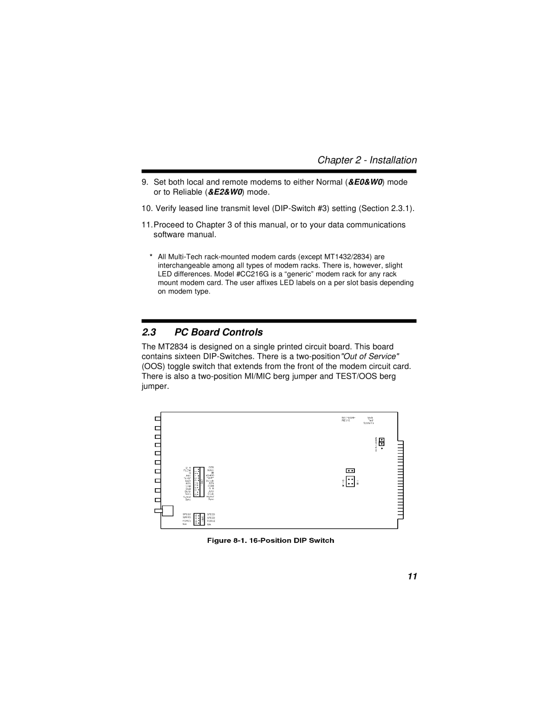
2.3PC Board Controls
The MT2834 is designed on a single printed circuit board. This board contains sixteen DIP-Switches. There is a two-position"Out of Service" (OOS) toggle switch that extends from the front of the modem circuit card. There is also a two-position MI/MIC berg jumper and TEST/OOS berg jumper.