Developer’s Guide
Embedded Modem MT5600SMI Family
SocketModem Developers Guide
Contents
114
Product Description Region
Introduction
Product Description
Developers Kit
Features
Sources of Additional Information
Technical Specifications
Maximum Component Height
Physical Dimensions
Pin Descriptions for Serial SocketModem Devices
Serial Pin Configurations
Available with or without LED Pins
Pin Signal Description Name Type
RXD
3V DC Power
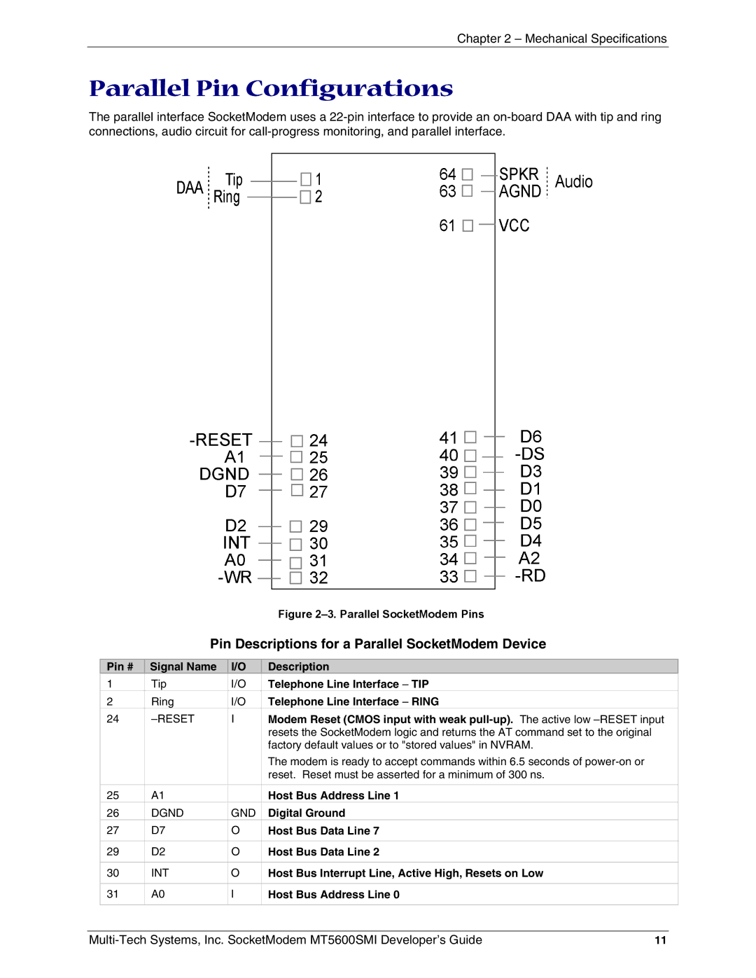
Parallel Pin Configurations
Speaker, Call Monitor
Agnd GND
Electrical Characteristics
Handling Precautions
Absolute Maximum Ratings
Operating Conditions
Current and Power Requirements
Parallel Host Bus Timing Table
Symbol Parameter Min Max Units
Parallel Host Bus Timing
Parallel Host Bus Read Parallel Host Bus Write
Overview
SocketModem Parallel Interface
Register BIT No Name
Parallel Interface Registers
IER Interrupt Enable Register Addr = 1, Dlab =
Register Signal Definitions
FCR7 FCR6
FCR Fifo Control Register Addr = 2, Write Only
Bit Interrupt Pending
IIR Interrupt Identifier Register Addr =
LCR Line Control Register Addr =
Bit 7 Divisor Latch Access Bit Dlab
Bit Data Terminal Ready DTR
MCR Modem Control Register Addr =
LSR Line Status Register Addr =
Bit 7 RX Fifo Error
Divisor Registers Addr = 0 and 1, Dlab =
MSR Modem Status Register Addr =
RBX RX Buffer Receiver Buffer Register Addr = 0, Dlab =
THR TX Buffer Transmitter Holding Register Addr = 0, Dlab =
Programmable Baud Rates
SCR Scratch Register Addr =
Receiver Data Available Interrupt
Receiver Character Timeout Interrupts
Receiver Fifo Interrupt Operation
Transmitter Fifo Interrupt Operation
AT Commands, S Registers, and Result Codes
Generic Modem Control Commands
Data Commands
Request Manufacturer Identification
Command Operating Mode Error Correction
Command Identification
Command
Request Revision Identification
Country of Installation
Command Restore Factory Configuration Profile
Request Model Identification
Command &Zn=x Store Telephone Number
Command Local Analog Loopback Test
Command Designate a Default Reset Profile
Command Store Current Configuration
Procedure
Command Plug and Play Vendor ID and Product Number
Command Load Flash Memory
Message Description
Upload Messages
Command Result Code Form
DTE-Modem Interface Commands
Command E Command Echo
Command Q Quiet Result Code Control
Command Extended Result Codes
Command Flow Control
Command Rlsd DCD Option
Command DTR Option
+IPR?
Command &R RTS/CTS Option
Command &S DSR Override
Command +IPR Fixed DTE Rate
Command +ILRR DTE-Modem Local Rate Reporting
Command +IFC DTE-Modem Local Flow Control
Dial Modifiers
Call Control Commands
Command D Dial
Command P Set Pulse Dial Default
Command T Set Tone Dial Default
Command Return to Online Data Mode
Command Answer
Command Disconnect Hang-Up
Command Select Pulse Dial Make/Break Ratio
Command Speaker Volume
Command Speaker Control
Command Select Guard Tone
Telephone Numbers
AT&V
Active Profile
Stored Profile
Protocol Lapm Compression
Command &V1 Display Last Connection Statistics
Termination Reason Local Request
Command Report Line Signal Quality
Command Single Line Connect Message Enable
Command Report Line Signal Level
Behavior in Voice Mode +FCLASS=8
Command -STE= Set Telephony Extension
Behavior in Data Mode +FCLASS=0
Connect
Examples
AT-STE=7
LINE-IN-USE
AT+VTX Dlep
AT-STE=3
No Dial Tone
AT+FCLASS=8
+MS Command Supported Rates
Command +MS Modulation Selection
Page
Modulation Reporting Control
+MR
Command Ccitt or Bell
Command Select µ-Law or A-Law Codec Type
Origfbk
Error Control Commands
Command +ES Error Control and Synchronous Mode Selection
Origrqst
Command +EFCS Bit Frame Check Sequence
Command +EB Break Handling in Error Control Operation
Command +ESR Selective Repeat
Call Termination Buffer Management
Error Control Reporting
Command +ER type Report the Current Error Control
Command Break Control
Command Transmit Break to Remote
Command -K MNP Extended Services
Command +DS44 Compression Select
Data Compression Commands
Command +DS Data Compression
Command +DR Data Compression Reporting
Command %C Enable/Disable Data Compression
Command +A8E V.8bis Operation Controls
V.8bis Commands
YYY
Command +A8I CI Signal Indication
Data Call State Model
Diagnostic Commands
Command #UD Last Call Status Report
Command Syntax
Digits
Monitoring an Active Connection
CallCleared codes from 3.6.4/V.58-1994
AT#UD Last Call Status Report Format Key Values Definition
V.34 Info bit report Bits Source bits Definition
Call Setup Result Codes Code Definition
Multimedia Modes Code Definition
DTE-DCE modes Code Definition
11. compressionActive from 3.2.2/V.58 Value Description
10. errorControl Active from 3.5.2/V.58 Value Description
Example Modem Response and Usage
Command Initial Cellular Power Level Setting
Compatibility Commands
Command Leased Line Operation
Command Enable Cellular Power Level Adjustment
Command +PCW Call Waiting Enable
FastConnect Commands
92 +P and -Q Commands
Command $F FastConnect Control
Initiate Modem-on-Hold
Modem-on-Hold Timer
Modem-on-Hold Hook Flash
Phase 1 and Phase 2 Control
PCM Upstream Ignore
Use Short Sequence
Force Full Startup Procedure on Next Connection
Enable Quick Connect Profile Save
Wait Time for Carrier, Silence, or Dial Tone
Registers
Reserved
Test Mode Bit-Mapped Options Status Indicates the test
Carrier Detect Response Time Supported for backward
General Bit-Mapped Options Status Indicates the status
Register Unit Range Default Description S21
Register Unit Range Default Description S27
Flow Control Bit-Mapped Options Status
Register Unit Range Default Description S36
General Bit-Mapped Options Status. Indicates the status
Register Unit Range Default Description S41
Pstn Transmit Attenuation Level. In non-PCM modes V.90 or
Register Unit Range Default Description S86
Register Unit Range Default Description S210
Short Form Long Form
Result Codes
+ER L APM
196 +MRR 197 198 199 200 201 202 203 204 205 206 207 208 209
Characters Detected Action Taken
Fax I/O Processing
DTE-to-Modem Transmit Data Stream
Modem-to-DTE Receive Data Stream
Fax Control Transmission
Fax Mode Selection
Fax Origination
Fax Answering
Fax Control Reception
Fax Data Reception
Fax Data Transmission
Mode Commands
Commands and Parameters
Mode Entry Commands
Fax Class 1 and Fax Class 1.0 Modulation Modes and Rates
Mod Modulation Training Modulation Mode and Rate
Transmit Facsimile
Command FTH Transmit Data with Hdlc Framing
Command +FRM Receive Facsimile
Command +FRH Receive Data with Hdlc Framing
Command +FCL Carrier Loss Timeout
Service Class 1 Commands
Command +FAR Adaptive Reception Control
DTE Inactivity Timeout
Double Escape Character Replacement
Command +FMR? Request Revision Identification
Command +FPR Fixed DTE Rate
Command +FMI? Request Manufacturer Identification
Command +FMM? Request Model Identification
Command +FLO Flow Control
Fax Class 1 Calling Sequence Transmitting a Single
Examples
Fax Class 1 Answering Sequence Receiving a Single
Voice
Voice Commands Overview
Voice Commands Function Configuration
DLE Shielded Event Codes Sent to the DTE
102
DLE Shielded Codes Sent to the Modem DCE
Can
+VNH Command Behavior Command Response
Voice Configuration Commands
Command +FCLASS=8 Select Voice Mode
Command +VNH Automatic Hang-up Control
Command +VTS Send Voice Tones
Basic Voice Commands
Command +VIP Voice Initialize All Parameters
Command +VRX Start Modem Receive Record
105
Command +VTX Start Modem Transmit Playback
Command +VGR Voice Gain Receive Record Gain
Example
106
Command +VGT Voice Gain Transmit Playback Volume
Command +VIT Voice Inactivity Timer DTE/Modem
+VSP=1
Command +VLS Analog Source/Destination Selection
+VLS Command Options
Label Primitives Description
108
S1T
109
Events Detectable in the Voice Mode per
Event Number Event Description Event Reporting
110
Command +VRA Ringback Goes Away Timer
Command +VRN Ringback Never Appeared Timer
Command +VSD Silence Detection Quiet and Silence
111
Command +VSM Compression Method Selection
112
Command +VTD Beep Tone Duration Timer
Command +VDR Distinctive Ring
113
Command +VDT Control Tone Cadence Reporting
114
Country Country Code
115
Test/Demo Board Components
116
Serial Test/Demo Board Block Diagram
Serial Test/Demo Board Block Diagram
5V / 3.3V Jumper JP6
117
Parallel Test/Demo Board Block Diagram
Parallel Test/Demo Board Block Diagram
EMC Approvals
Approvals Product Safety and EMC
Safety Certifications
Telecom Certifications
119
Regulatory Design Considerations
Hardware Considerations
120
EMC
121
Other Design Considerations
PC Board Layout Guidelines
122
Safety
Electromagnetic Interference EMI Considerations
123
5V Tolerant Inputs for 3.3V Modules
124
Regulatory Compliance
Regulatory Requirements for the United States
125
MT5600SMI
126
Current Label Content and Format as of August
127
Regulatory Requirements for Canada
128
IC XXXXXX-ZZZZZZZZ Where
129
New Zealand Telecom Warning Notice
South African Statement
130
EMC, Safety, and R&TTE Directive Compliance
International Modem Restrictions
131
Index
132
Enable quick connect profile save command -QCPS
133
Serial Test/Demo Board Components
134