Model LS600
Diesel engine exhaust and some
Mayco LS600 Pump Operation and Parts Manual REV. #4 9/15/11
LS600 Pump -TABLE of Contents
Parts Ordering Procedures
Ordering parts has never been easier
LS600 Pump Safety Message Alert Symbols
Hazard Symbols
LS600 Pump Safety Message Alert Symbols
Always wear approved respiratory protection
General Safety
LS600 Pump Rules for Safe Operation
Serious burns
Maintenance Safety
Transporting
Towing
Battery
Emergencies
Always know the location of the nearest and first aid kit
Mayco LS600 Pump Operation and Parts Manual REV. #4 9/15/11
LS600 Pump Specifications
LS600 Pump Dimensions
Dimensions
LS600 Pump Important Hand Signals
Operation Hand Signals
LS600 Pump General Information
Concrete MIX Design
LS600 Pump General Information
Mud Jacking, high pressure grouting
LS600 Pump HOW IT Works
Pumping Cycle
LS600 Pump Pump Components
Major Pump Components
LS600 Pump Pump Components
Input cable into this connector
LS600 Pump Digital Control Panel Components
Counter
LS600 Pump Digital Readout Screen
Primary Screen
LS600 Pump Engine Components
Air Intake Attach the Air Filter Hose to the Air Intake
LS600 Pump Inspection
Fuel Check
Before Starting
Check fastening nuts and bolts for tightness
LS600 Pump Inspection
Engine OIL Check
Remove the engine oil dipstick from its holder Figure
Hydraulic OIL Check
Hydraulic Oil Filler Hole
LS600 Pump SET-UP
Location of Pump
Rear Stabilizer Jacks
Hydraulic Rear Stabilizer Jacks Optional
LS600 Pump START-UP Procedure
Starting Procedure
LS600 Pump Operation
Hose Lubrication
Before pumping, it is necessary to lubricate the hose
Pumping
Hydraulic Oil Temperature Gauge
Remote Control Optional
Reinstall the control panel and tighten the 2 screws
Radio Remote Control
Radio Remote Control Buttons Operation
Cable Remote Control
Cable Remote Control Operation
LS600 Pump Operation
LS600 Pump Pumping Information
Remixtures
Downhill Pumping
Vertical Pumping
LS600 Pump Pumping Information
SNAP-JOINT Couplings
NEW Pumps
Effects of Heat and Excessive Time on Concrete
Clearing the System After MIX SET UP
Clearing Concrete Blockage
Reverse Pumping Procedure
Shuttle Tube Inspection Procedure
Clearing Shuttletube Blockage
Remix the concrete in the hopper
LS600 Pump Maintenance Pump
Cleaning the Pump and Delivery System
LS600 Pump Maintenance Pump
Hydraulic OIL System Maintenance
LS600 Pump Maintenance Pump
Battery Maintenance
Brake System
Cleaningthe Lubrication BOX
Cylinder Lubrication BOX
Accumulator Circuit
LS600 Pump Maintenance Pump
Cylinder CUP Replacement Procedure
Size and type of aggregate Type of concrete being pumped
Wear Plate and Ring Replacement Procedure
Wear Plate Installation
Wear Ring installation
Changingthe Wear Plate and Ring
Wheel Bearings
Extended Storage Instructions
Pressure Test
LS600 Pump Maintenance Trailer
Manually Adjusting the Brakes
Trailer Brakes
Hydraulic Brakes
LS600 Pump Maintenance Trailer
Adjustable Channel
Wheel Hub Adjustment
Wheel Bearings Hubs
Torsion Suspension
Tube
LS600 Pump -TRAILER Safety Guidelines
Common Causes for Loss of Trailer
Trailer Towing Guidelines
LS600 Pump -TRAILER Safety Guidelines
Driving Conditions
Coupling to the Tow Vehicle
Reporting Safety Defects
Inoperable Brakes, Lights or Mirrors
Trailer Towing Tips
Trailer VIN Tag
Determines Gawr
Electrical Connector
Safety Chains
Trailer Lighting and Braking Connector
Tow Vehicle
Coupler Types
Ball Hitch Coupler
Ball Hitch Coupling Mechanism
Attaching Safety Chain
Breakaway Brake System
Breakaway Cable Surge Brake System
Connecting Trailer Lights
Uncoupling the Ball Hitch
Unsafe Tires, Lug Nuts or Wheels
Determining Load Limit of Trailer
Tire and Loading Information
Step
Determining Load Limit of Tow Vehicle Step
Tire Fundamentals
Tires
Uniform Tire Quality Grading Standards Utqgs
Tire Safety Tips
Tire Repair
Replacing Worn or Damaged Tires
Load Range
Wheel Rims
Wheels, Bearings and Lug Nuts
Lug Nut Torque Requirements
Start all wheel lug nuts by hand
LS600 Pump -TRAILER Safety Guidelines
Lights and Signals
LS600 Pump Troubleshooting Pump
Pump Troubleshooting
LS600 Pump Troubleshooting Pump
PSI
LS600 Pump -TROUBLESHOOTING Engine
Engine Troubleshooting
LS600 Pump -TROUBLESHOOTING Trailer Brake System
Brake System Troubleshooting
Refer to for the location of components for troubleshooting
Malfunction
LS600 Pump Troubleshooting Electrical
Probable Cause Solution
Location of Components for Electrical Troubleshooting
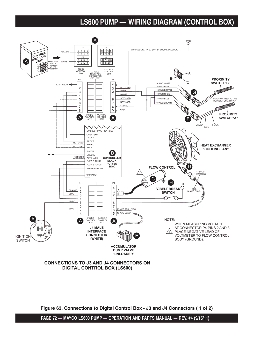
LS600 Pump Wiring Diagram Control BOX
Control Rear BOX View
LS600 Pump Wiring Diagram Control BOX
Ignition Switch
LS600 Pump Wiring Diagram Control BOX
LS600 Pump Wiring Diagram Engine START/SHUTDOWN Relay
LS600 Pump Wiring Diagram Hopper Vibrator
Optional Hopper Vibrator Wiring Diagram
LS600 Pump Hydraulic System Diagram
Hydraulic System Diagram
LS600 Pump Manifold Block Ports
Manifold Block Ports
Appendix Concrete MIX Information
Appendix Concrete MIX Information
Appendix Slumptest Procedure
Several samples at three or more regular intervals
Mayco LS600 Pump Operation and Parts Manual REV. #4 9/15/11
Appendix Recommended Shotcrete System
Recommended Shotcrete System
13 EM23808D Nozzle ASSEMBLY, 2 H-D
Recommended Shotcrete System NO. Part no Part Name
10 EM23101 AIR Vibrator Assy
11 EM28131D 2x2 Elbow 90º 12 EM24841 HOSE, 2x25’ H-D w/ENDS
Appendix Recommended Shotcrete Accessories
Recommended Shotcrete Accessories
Has Passed Through the Entire Hose Length
Part Name QTY Remarks
LS600 Pump Explanation of Code in Remarks Column
Xxxxx only Not Used on
LS600 Pump Suggested Spare Parts
LS600 Pump Nameplate and Decals
LS600 Pump Nameplate and Decals
LS600 Pump Nameplate and Decals
DECAL, MQ/MAYCO LS600 Logo TBD DECAL, Fault Locator
TBD DECAL, Impact Hazard
Included W/ITEM
DECAL, Hydraulic OIL only
LS600 Pump Frame Assy
FRAME, Main
Jack STAND, Front
Clevis PIN
PIN
LS600 Pump Axle ASSY. RIGHT/LEFT
LS600 Pump Axle ASSY. RIGHT/LEFT
AXLE, Torsion BAR Assy
LS600 Pump Brake Line Assy
KIT, Main Brake Line
LS600 Pump Brake Light Assy
LS600 Pump Brake Light Assy
29242
Brake Light Assy
29207
LS600 Pump -TRAILER Hitch Assy
LS600 Pump -TRAILER Hitch Assy
WASHER, Flat 1/2
LS600 Pump Battery Assy
Battery BOX W/ Belt
Battery 12V 125A
Battery Cable Positive
Battery Cable Negative
LS600 Pump Hopper Assy
Housing
Hopper Assy
Hopper Seal
Remixer Shaft
LS600 Pump Hopper Attachment Assy
LS600 Pump Hopper Attachment Assy
LS600 Pump Hopper Interior Assy
LS600 Pump Hopper Interior Assy
LS600 Pump Shuttle Cylinder Assy
LS600 Pump Shuttle Cylinder Assy
LS600 Pump Lubrication Pistons Assy
LS600 Pump Lubrication Pistons Assy
LS600 Pump Lubrication Pistons Assy
Adjustment ROD, Proximity Switch
BRACKET, Adjustment ROD
BOLT, HEX Head 5/16 NC X 1 IN. G5
WASHER, Lock 5/16
LS600 Pump Fueltank Assy
LS600 Pump Fuel Tank Assy
LS600 Pump Heat Exchanger Assy
LS600 Pump Heat Exchanger Assy
LS600 Pump Accumulator Assy
LS600 Pump Accumulator Assy
Part Name QTY
LS600 Pump Remixer Control Assy
LS600 Pump Remixer Control Assy
LS600 Pump Lubrication Panel
Position Location
34 in .1 m
26 in. .85 m
Connector
LS600 Pump Lubrication Panel
HOSE, Plastic
HOSE, Steel
LS600 Pump Engine Cover Assy
LS600 Pump Engine Cover Assy
COVER, TOP
COVER, Front Engine
Document BOX
LS600 Pump Hydraulictank Assy
LS600 Pump Hydraulictank Assy
HOSE, 4000 PSI Main Gauge
LS600 Pump Engine Assy
FILTER, OIL Engine
FILTER, Fuel Engine
Deflector
Reduction TUBE, Exhaust
LS600 Pump Engine AIR Filter Assy
LS600 Pump Engine AIR Filter Assy
LS600 Pump -THROTTLE Assy
Seal Connector
CONNECTOR, DIN PG9
Support BASE, Accelerator
HEX NUT 1/4
LS600 Pump Water Separator Assy
LS600 Pump Water Separator Assy
EM509449
EM492356
LS600 Pump HYD. Pump Assy
TBD Ring
Clamp 2
HOSE, Suction 2
ADAPTER, Suction Pipe
LS600 Pump Manifold Assy
Replaces EM98109
EMBK227
Pilot VALVE, Shuttle
Includes Item W
LS600 Pump Control BOX Assy
Control BOX Assy
Ignition Switch Assy
Emergency Stop Switch Assy
Contact BLOCKS, Emergency Switch
Flow Direction Switch Assy
LS600 Pump Control BOX Harnesses Assy
Control BOX Harnesses Assy
Wire Harness 1
Wire Harness
FUSE, 30 AMP
Conductive Divider 3/8
LS600 Pump Remote Control Cable Assy
Remote Control Cable Assy
Switch
CONNECTOR, Ring 3/16
Guard Switch Aluminum
Junction BOX
LS600 Pump Hydraulic Stabilizer ASSY. Optional
LS600 Pump Hydraulic Stabilizer ASSY. Optional
Terms and Conditions of Sale Parts
Freight Policy
Mayco Pumpwarranty
Mechanical Drive Models
HERE’S HOW to GET Help