μPD75P308
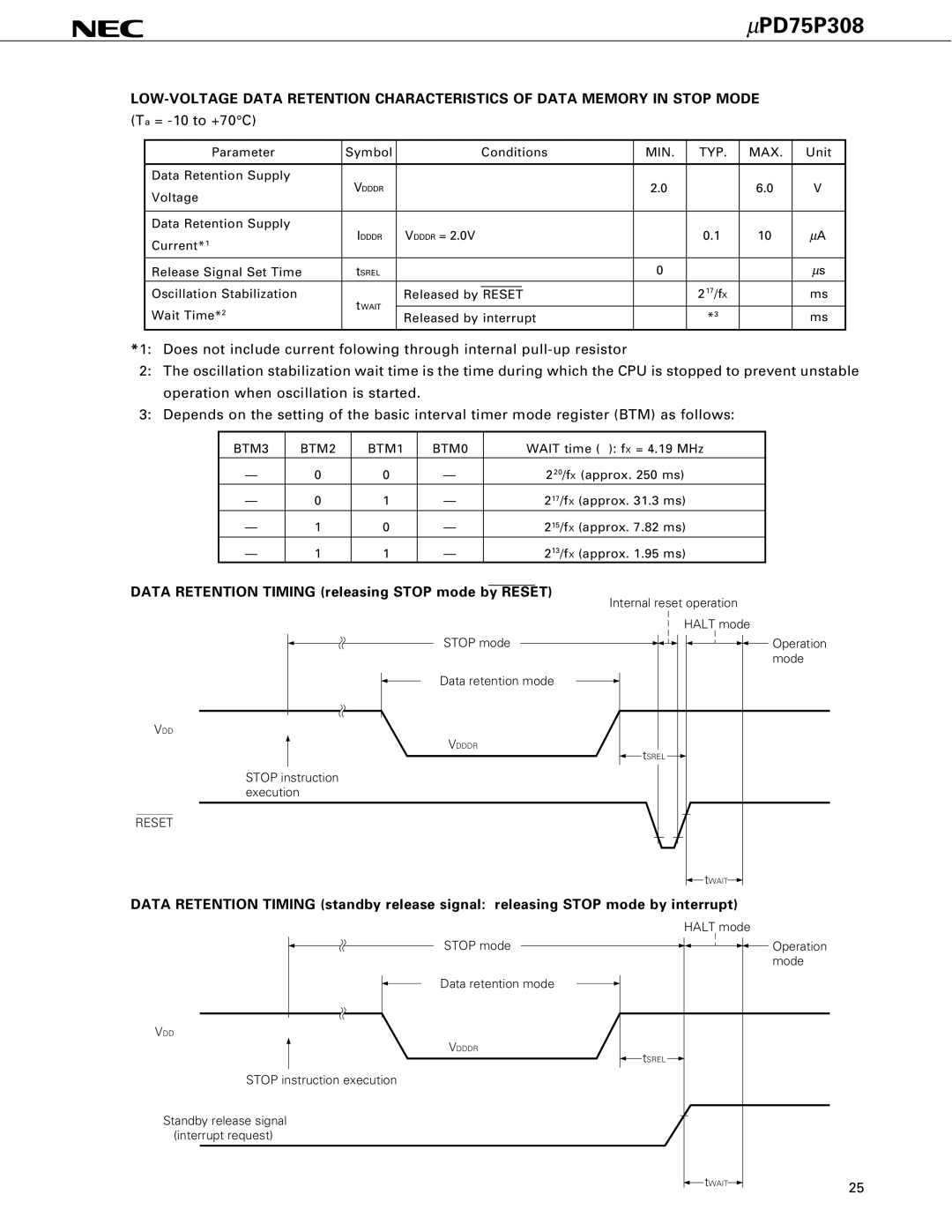
(Ta = -10 to +70°C)
Parameter | Symbol |
| Conditions | MIN. | TYP. | MAX. | Unit | |
|
|
|
|
|
|
|
|
|
Data Retention Supply | VDDDR |
|
|
| 2.0 |
| 6.0 | V |
Voltage |
|
|
|
| ||||
|
|
|
|
|
|
|
| |
|
|
|
|
|
|
|
|
|
Data Retention Supply | IDDDR | VDDDR = 2.0V |
| 0.1 | 10 | μA | ||
Current*1 |
| |||||||
|
|
|
|
|
|
|
| |
|
|
|
|
|
|
|
|
|
Release Signal Set Time | SREL |
|
|
| 0 |
|
| μs |
t |
|
|
|
|
|
|
| |
Oscillation Stabilization |
|
|
|
|
| 217/fX |
| ms |
tWAIT | Released by RESET |
|
| |||||
Wait Time*2 |
|
|
|
|
|
|
| |
Released by interrupt |
| *3 |
| ms | ||||
|
|
| ||||||
|
|
|
|
|
|
|
|
|
*1: Does not include current folowing through internal
2:The oscillation stabilization wait time is the time during which the CPU is stopped to prevent unstable operation when oscillation is started.
3:Depends on the setting of the basic interval timer mode register (BTM) as follows:
BTM3 | BTM2 | BTM1 | BTM0 | WAIT time ( ): fX = 4.19 MHz |
— | 0 | 0 | — | 220/fX (approx. 250 ms) |
— | 0 | 1 | — | 217/fX (approx. 31.3 ms) |
— | 1 | 0 | — | 215/fX (approx. 7.82 ms) |
— | 1 | 1 | — | 213/fX (approx. 1.95 ms) |
DATA RETENTION TIMING (releasing STOP mode by RESET)
Internal reset operation
HALT mode
STOP mode
Data retention mode
VDD
VDDDR
![]() tSREL
tSREL ![]()
STOP instruction execution
Operation mode
RESET
![]() tWAIT
tWAIT![]()
DATA RETENTION TIMING (standby release signal: releasing STOP mode by interrupt)
HALT mode
STOP mode
Data retention mode
VDD
VDDDR
![]() tSREL
tSREL ![]()
STOP instruction execution
Standby release signal (interrupt request)
Operation mode
tWAIT | 25 |
|