|
| μPD75P308 |
TYPE |
|
|
|
| VDD |
|
| P.U.R. |
| P.U.R. | |
| enable | |
|
| |
|
| IN/OUT |
data |
| |
|
| |
output |
|
|
disable |
|
|
| P.U.R. : |
|
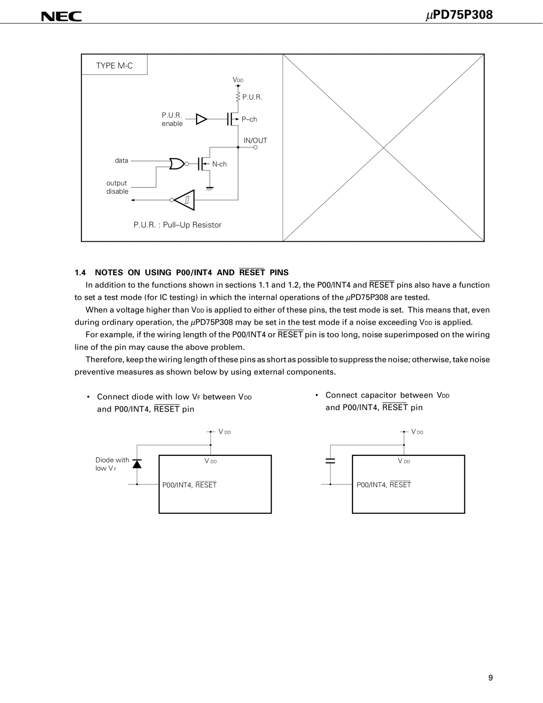
1.4NOTES ON USING P00/INT4 AND RESET PINS
In addition to the functions shown in sections 1.1 and 1.2, the P00/INT4 and RESET pins also have a function to set a test mode (for IC testing) in which the internal operations of the μPD75P308 are tested.
When a voltage higher than VDD is applied to either of these pins, the test mode is set. This means that, even during ordinary operation, the μPD75P308 may be set in the test mode if a noise exceeding VDD is applied.
For example, if the wiring length of the P00/INT4 or RESET pin is too long, noise superimposed on the wiring line of the pin may cause the above problem.
Therefore, keep the wiring length of these pins as short as possible to suppress the noise; otherwise, take noise preventive measures as shown below by using external components.
•Connect diode with low VF between VDD and P00/INT4, RESET pin
V DD
Diode with |
| V DD |
| ||
low V F |
|
|
•Connect capacitor between VDD and P00/INT4, RESET pin
V DD
V DD
![]() P00/INT4, RESET
P00/INT4, RESET
P00/INT4, RESET
9