μPD75P308
1. PIN FUNCTIONS
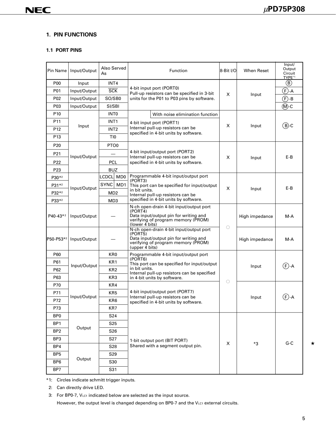
1.1 PORT PINS
|
| Also Served |
|
|
|
|
| Input/ | |||
Pin Name | Input/Output |
| Function | When Reset | Output | ||||||
|
| As |
|
|
|
|
| Circuit | |||
|
|
|
|
|
|
|
|
|
|
| TYPE*1 |
P00 | Input |
| INT4 |
|
|
| B | ||||
|
|
|
|
|
|
|
|
|
| ||
|
|
|
|
|
|
|
|
|
| ||
P01 | Input/Output |
| SCK |
|
|
| F | ||||
| X | Input |
| ||||||||
|
|
|
|
|
|
|
| ||||
P02 | Input/Output | SO/SB0 | units for the P01 to P03 pins by software. |
|
|
| F | ||||
|
|
|
|
|
|
|
|
|
|
|
|
P03 | Input/Output | SI/SBI |
|
|
|
|
| M | |||
|
|
|
|
|
|
|
|
|
|
|
|
P10 |
|
| INT0 |
| With noise elimination function |
|
|
|
| ||
|
|
|
|
|
|
|
|
|
|
|
|
P11 | Input |
| INT1 | X | Input | B | |||||
P12 |
| INT2 | Internal | ||||||||
|
|
|
|
|
| ||||||
|
| specified in |
|
|
|
| |||||
|
|
|
|
|
|
|
|
|
| ||
P13 |
|
| TI0 |
|
|
|
| ||||
|
|
|
|
|
|
|
| ||||
|
|
|
|
|
|
|
|
|
|
|
|
P20 |
| PTO0 |
|
|
|
|
|
| |||
|
|
|
|
|
|
|
|
|
| ||
P21 | Input/Output |
| — |
|
|
|
| ||||
| Internal | X | Input | ||||||||
P22 |
| PCL | |||||||||
|
| specified in |
|
|
|
| |||||
P23 |
|
| BUZ |
|
|
|
|
|
| ||
P30*2 |
| LCDCL | MD0 | Programmable |
|
|
|
| |||
|
|
|
|
|
| (PORT3) |
|
|
|
| |
|
| SYNC | MD1 |
|
|
|
| ||||
P31*2 | Input/Output | This port can be specified for input/output | X | Input | |||||||
P32*2 |
| MD2 | in bit units. | ||||||||
|
|
|
|
|
| ||||||
|
| Internal |
|
|
|
| |||||
P33*2 |
|
| MD3 | specified in |
|
|
|
| |||
|
|
|
|
|
|
|
|
|
| ||
|
|
|
|
|
| (PORT4) |
|
|
|
| |
Input/Output |
| — | Data input/output pin for writing and |
| High impedance | ||||||
|
|
|
|
|
| verifying of program memory (PROM) |
|
|
|
| |
|
|
|
|
|
| (lower 4 bits) | ● |
|
|
| |
|
|
|
|
|
|
|
|
| |||
|
|
|
|
|
|
|
|
|
| ||
|
|
|
|
|
| (PORT5) |
|
|
|
| |
Input/Output |
| — | Data input/output pin for writing and |
| High impedance | ||||||
|
|
|
|
|
| verifying of program memory (PROM) |
|
|
|
| |
|
|
|
|
|
| (upper 4 bits) |
|
|
|
| |
P60 |
|
| KR0 | Programmable |
|
|
|
| |||
|
|
|
|
|
| (PORT6) |
|
|
|
| |
P61 |
|
| KR1 |
|
|
|
| ||||
Input/Output |
| This port can be specified for input/output |
| Input | F | ||||||
|
|
|
|
|
| ||||||
P62 |
| KR2 | in bit units. |
| |||||||
|
|
|
|
|
| ||||||
|
| Internal |
|
|
|
| |||||
|
|
|
|
|
|
|
|
|
| ||
P63 |
|
| KR3 |
|
|
|
| ||||
|
| in | ● |
|
|
| |||||
|
|
|
|
|
|
|
|
|
|
| |
P70 |
|
| KR4 |
|
|
|
|
| |||
|
|
|
|
|
|
|
| ||||
|
|
|
|
|
|
|
|
| |||
P71 | Input/Output |
| KR5 |
|
|
|
| ||||
|
|
|
|
| Internal |
| Input | F | |||
P72 |
| KR6 |
| ||||||||
|
| specified in |
|
|
|
| |||||
|
|
|
|
|
|
|
|
|
| ||
P73 |
|
| KR7 |
|
|
|
|
|
| ||
|
|
|
|
|
|
|
|
|
|
| |
BP0 |
|
| S24 |
|
|
|
|
|
| ||
|
|
|
|
|
|
|
|
|
|
| |
BP1 | Output |
| S25 |
|
|
|
|
|
| ||
|
|
|
|
|
|
|
|
|
|
| |
BP2 |
| S26 |
|
|
|
|
|
| |||
|
|
|
|
|
|
|
| ||||
|
|
|
|
|
|
|
|
|
|
| |
BP3 |
|
| S27 | X | *3 |
| |||||
|
|
|
|
|
|
| |||||
BP4 |
|
| S28 | Shared with a segment output pin. |
| ||||||
|
|
|
|
|
| ||||||
|
|
|
|
|
|
|
|
|
|
| |
BP5 | Output |
| S29 |
|
|
|
|
|
| ||
|
|
|
|
|
|
|
|
|
|
| |
|
|
|
|
|
|
|
|
|
|
| |
BP6 |
| S30 |
|
|
|
|
|
| |||
|
|
|
|
|
|
|
| ||||
|
|
|
|
|
|
|
|
|
|
| |
BP7 |
|
| S31 |
|
|
|
|
|
| ||
|
|
|
|
|
|
|
|
|
|
|
|
*1: Circles indicate schmitt trigger inputs.
2:Can directly drive LED.
3:For
However, the output level is changed depending on
★
5