μPD75P308
2. DIFFERENCES BETWEEN μPD75P308 AND μPD75308
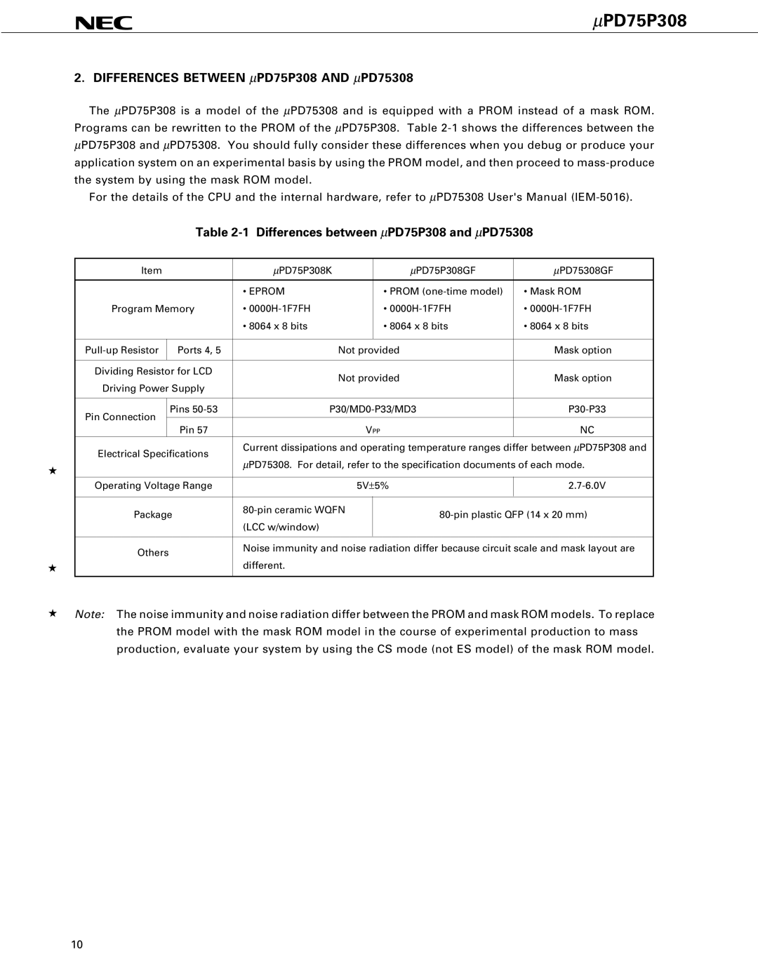
The μPD75P308 is a model of the μPD75308 and is equipped with a PROM instead of a mask ROM. Programs can be rewritten to the PROM of the μPD75P308. Table
For the details of the CPU and the internal hardware, refer to μPD75308 User's Manual
Table
| Item |
| μPD75P308K |
|
| μPD75P308GF | μPD75308GF | |
|
|
|
|
|
|
|
|
|
|
|
|
| • EPROM |
|
| • PROM | • Mask ROM |
| Program Memory | • |
|
| • | • | ||
|
|
|
| • 8064 x 8 bits |
|
| • 8064 x 8 bits | • 8064 x 8 bits |
|
|
|
|
|
|
|
| |
|
| Ports 4, 5 |
| Not provided | Mask option | |||
|
|
|
|
|
|
|
| |
| Dividing Resistor for LCD |
| Not provided | Mask option | ||||
| Driving Power Supply |
| ||||||
|
|
|
|
|
| |||
|
|
|
|
|
| |||
| Pin Connection |
| Pins | |||||
|
|
|
|
|
|
|
| |
|
| Pin 57 |
|
| VPP | NC | ||
|
|
|
|
| ||||
| Electrical Specifications | Current dissipations and operating temperature ranges differ between μPD75P308 and | ||||||
| μPD75308. For detail, refer to the specification documents of each mode. | |||||||
★ |
|
|
| |||||
|
|
|
|
|
|
|
| |
| Operating Voltage Range |
|
| 5V±5% | ||||
|
|
|
|
|
|
|
| |
| Package |
| ||||||
|
|
|
| |||||
|
|
|
| (LCC w/window) |
|
|
|
|
|
|
|
|
|
| |||
| Others |
| Noise immunity and noise radiation differ because circuit scale and mask layout are | |||||
|
|
|
|
|
|
| ||
★ |
|
|
| different. |
|
|
|
|
|
|
|
|
|
|
|
|
|
★Note: The noise immunity and noise radiation differ between the PROM and mask ROM models. To replace the PROM model with the mask ROM model in the course of experimental production to mass production, evaluate your system by using the CS mode (not ES model) of the mask ROM model.
10