Service MA NUA L Citiz Coffee MA Chines
Contents
Repairs
130
Content Upda TES
Prefa CE
Version
To contact with both cir cuit conductors
Genera L SA Fety Notes
Model Overview
Model range
With core unit Drange With core unit Crange
Core unit versions
rangeCrange
Different components range
Overview core unit, Drange
MA in Components
Interior view core unit, Drange
Overview core unit, Crange
Interior view core unit, Crange
Overview model Citiz
Overview model Citiz & milk
Overview milk frother AERO3
Overview model Citiz & Co
Fluid System
Water circuit diagram of core unit all Citiz versions
Water circuit of models Citiz/Citiz & milk
Water circuit of model Citiz & Co
Rating plates
Technica L DA TA
Examples of brand specific rating plates
Nespresso, EUversion
Koenig, CHversion
DeLonghi, EUversion
Magimix, EUversion
Krups, EUversion
Turmix, ATversion
Rating plate details
Rating plate of milk frother model Citiz & milk
Decoding the alphanumeric serial number
Example
Technical data of coffee machines
Summary of technical data
Pump
Temperatures
Capacities
Various data
Technical data of milk frother model Citiz & milk
Dimensions and weight model Citiz
Temperature
Performance data
Dimensions and weight milk frother
Dimensions and weight model Citiz & milk
Dimensions and weight model Citiz & Co
General information
Opera Tion
Status indication
Status indication of coffee machine
Button
Status indication of milk frother AERO3
Machine status etc Operating button Light signal
Enter mode Actions Exit mode
Machine modes
Machine modes of Citiz coffee machines
Machine mode
Machine mode Enter mode Actions Exit mode
Machine modes of milk frother AERO3
Program/reset fill up level
Resetting the fill up level
Programming the fill up level
Empty water system
Daily maintenance and cleaning
MA Intena NCE
Before first coffee or at the start of day
After last coffee or at the end of day
Milk frother of model Citiz & milk
Descaling
Descaling procedure for models Citiz and Citiz & milk
Observe the safety instructions on the descaler package
I N T E N a N C E
Rinse thoroughly to remove any residue
Descaling procedure for model Citiz & Co
Do not open handles dur ing descaling process
I N T E N a N C E
I N T E N a N C E
Check Error symptoms
Troub L Eshooting
Check list for coffee machine all models
Work
Check Error symptoms Measure
Check list for milk frother
Error symptoms Measure Repair work
Check
Further measures / repair Work
Safety instructions
Repa IRS
Repair and mounting tips
Bottom of platform
Designation of spare parts
Wiring arrangement
Electrostatic discharge protection
Residual water
Tools and accessories
General disassembly
Platform disassembly model Citiz
Bottom cover
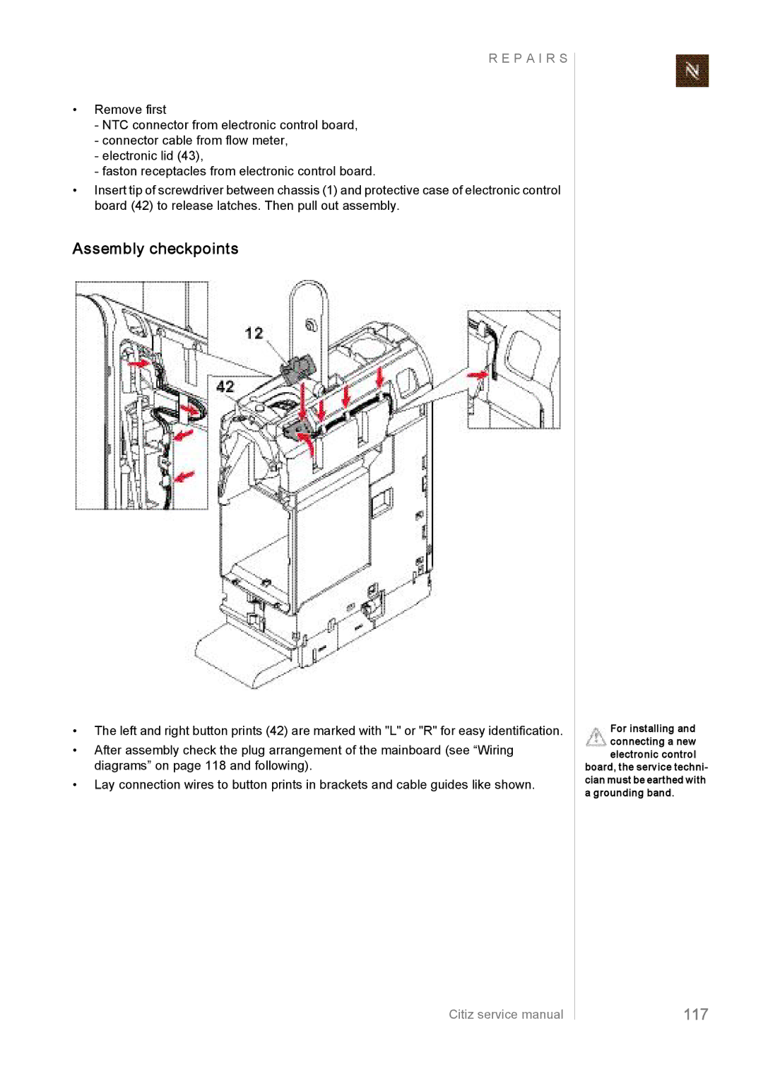
Assembly checkpoints
Replacing water tank connector
Replacing mains switch
Assembly checkpoints
Replacing power cord
Wiring with twocore power cord
Wiring with threecore power cord
Removing core unit
Use apair of flat pliers
Assembly checkpoints
Platform disassembly model Citiz & milk
P a I R S
P a I R S
Assembly checkpoints
Replacing water tank connector
Assembly checkpoints
Replacing milk frother connector
Receptacles
Replacing power cord
Assembly checkpoints
Removing core unit
Tacle
Assembly checkpoints
Platform disassembly model Citiz & Co
Core units are
If necessary use a screwdriver to remove protective cover
Assembly checkpoints
Replacing water tank connector
Replacing mains switch
Assembly checkpoints
Replacing power cord
Assembly checkpoints
Removing core units
Assembly checkpoints
Remove left side panel
Disassembly of core unit, Crange
P a I R S
Remove blind
Remove right side panel
Remove front cover with outlet
Remove cover
Assembly checkpoints
Replacing compact brewing unit
Assembly checkpoints
General
Replacing pump
Replacing pump assembly
Seat for the fork wrench
Assembly checkpoint
Replacing flow meter
101
Replacing automatic priming device APD
103
Replacing thermoblock with NTC sensor and fine wire fuses
Assembly checkpoint NTC temperature sensor
Replacing NTC temperature sensor
Replacing fine wire fuses
105
Assembly checkpoints thermoblock
Assembly checkpoints fine wire fuses
107
Replacing electronic control board with button prints
P a I R S
Disassembly of core unit, Drange
Remove outlet
109
Remove right side panel
111
Swing up and remove right side panel
113
Closing handle should be opened
115
Refer to page 114 for removing cover
117
Wiring diagrams
Wiring diagrams model Citiz
Wiring diagram 220 V 240 V IEC model Citiz, EF 483/484
119
Wiring diagram 120 V UL USA/Canada model Citiz, EF 483/484
P a I R S
121
Wiring diagram 110 V IEC Taiwan model Citiz, EF 483/484
123
Wiring diagram 100 V IEC Japan model Citiz, EF 483/484
Wiring diagrams model Citiz & milk, EF 485/486
125
P a I R S
127
Wiring diagrams model Citiz & Co, EF 487/488
129
Function Tests
Required equipment
Overview
131
Citiz pressure gauge adapter
Measure flow rate
133
Pressure and leakage checks
Preparations
135
Test run
Measure coffee temperature
137
Coffee temperature should be 86 C ± 3 C 187 F ± 5.4 F
Milk frother tests
Measure hot milk temperature
Measure milk froth ratio
Prerequisite
139
NTC temperature sensor functionality
NTC Diagram
NTC temperature NTC min. resistance NTC max. resistance
Measurement table
What coffee machine has to be tested and when?
Protective earth PE continuity test
General
141
Resistance must be lower than Ohm
Test sequence
What to do if the protective earth continuity test fails
143
Additional test for coffee machine Citiz & milk
What coffee machines have to be tested and when?
Protective insulation test
145
Additional tests for coffee machine Citiz & milk
147
What to do if the insulation test fails
10.1Model Citiz, core unit Drange EF
Expl Osion DRA Wings
149
Model Citiz, core unit Crange EF
Model Citiz & milk, core unit Drange EF
151
Model Citiz & milk, core unit Crange EF
Model Citiz & Co, core unit Drange EF
153
Model Citiz & Co, core unit Crange EF
PA RTS L IST
Pos.Component
Remark
Pos Component
155
Connection cable UL
157
T E S