Reference Guide for the Model RT311 and RT314 Internet Access Gateway Routers
The Router’s Rear Panel
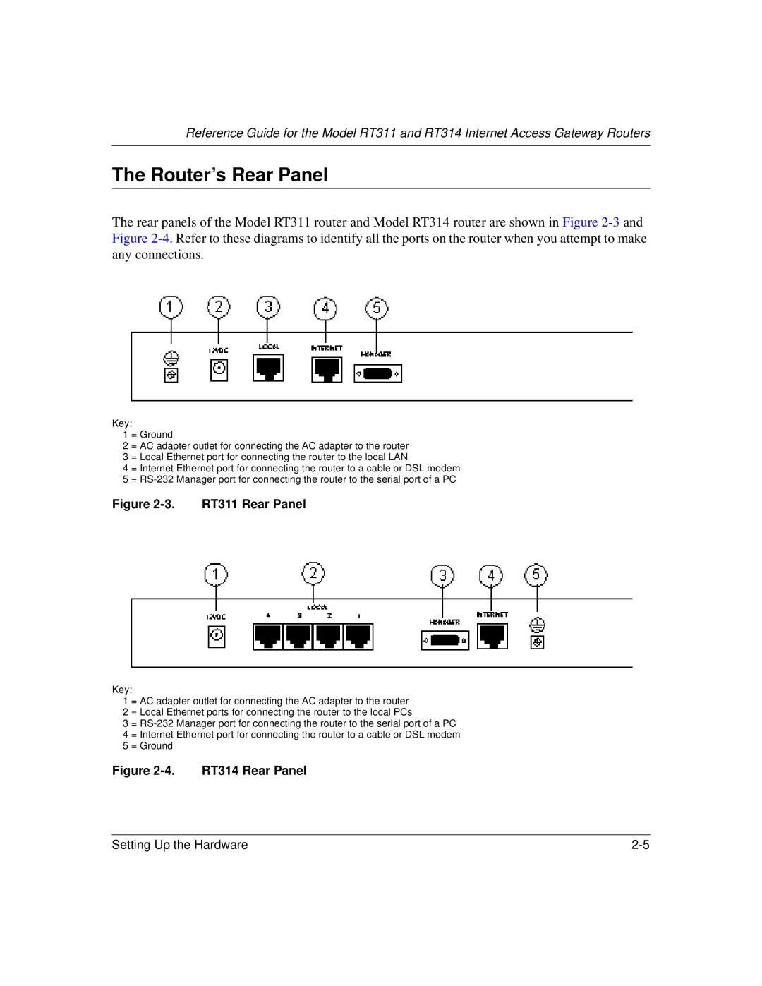
The rear panels of the Model RT311 router and Model RT314 router are shown in Figure
Key:
1 = Ground
2 = AC adapter outlet for connecting the AC adapter to the router 3 = Local Ethernet port for connecting the router to the local LAN
4 = Internet Ethernet port for connecting the router to a cable or DSL modem 5 =
Figure 2-3. RT311 Rear Panel
Key:
1 = AC adapter outlet for connecting the AC adapter to the router
2 = Local Ethernet ports for connecting the router to the local PCs
3 =
Figure 2-4. RT314 Rear Panel
Setting Up the Hardware |