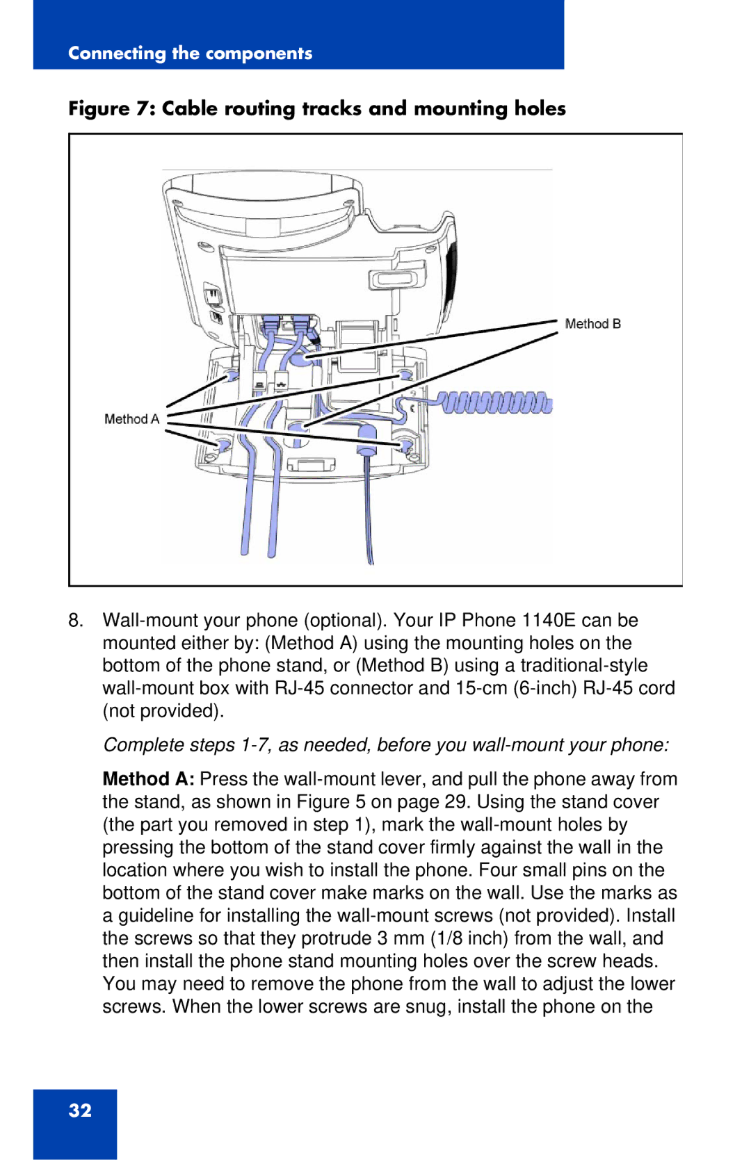
8.Wall-mount your phone (optional). Your IP Phone 1140E can be mounted either by: (Method A) using the mounting holes on the bottom of the phone stand, or (Method B) using a traditional-stylewall-mount box with RJ-45 connector and 15-cm(6-inch)RJ-45 cord (not provided).
Complete steps 1-7, as needed, before you wall-mount your phone:
Method A: Press the wall-mount lever, and pull the phone away from the stand, as shown in Figure 5 on page 29. Using the stand cover (the part you removed in step 1), mark the wall-mount holes by pressing the bottom of the stand cover firmly against the wall in the location where you wish to install the phone. Four small pins on the bottom of the stand cover make marks on the wall. Use the marks as a guideline for installing the wall-mount screws (not provided). Install the screws so that they protrude 3 mm (1/8 inch) from the wall, and then install the phone stand mounting holes over the screw heads. You may need to remove the phone from the wall to adjust the lower screws. When the lower screws are snug, install the phone on the