Installing the ARN
Understanding the ARN Module Locations
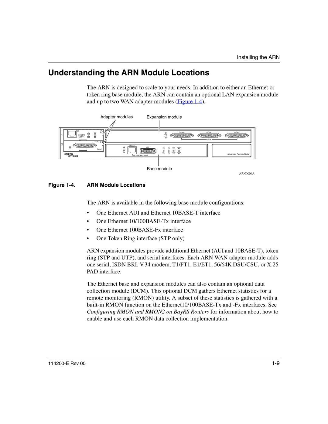
The ARN is designed to scale to your needs. In addition to either an Ethernet or token ring base module, the ARN can contain an optional LAN expansion module and up to two WAN adapter modules (Figure
Adapter modules | Expansion module |
| U | D | B1 |
|
| RLSD3 |
|
| COM3 | COM4 | COM5 |
1 |
|
|
|
|
|
| |||||
ISDN BRI |
|
|
|
| RLSD4 |
|
|
|
|
| |
DD | B2 |
|
|
|
|
|
|
|
| ||
| withNT1 |
|
|
|
| RLSD5 |
|
|
|
|
|
|
|
|
|
|
|
|
|
|
| Serial |
|
|
|
| COM |
|
|
|
|
|
|
|
|
2 |
|
|
|
| 10BaseT |
|
|
|
|
|
|
| RLSD |
|
| Tx |
|
|
|
|
|
| |
|
|
|
|
| AUI | Run | Pwr | Base | Expansion |
|
|
|
|
| Serial | Rx |
| Boot | RPS | Adapter1 | DCM |
|
|
|
|
|
|
|
|
| |||||
|
|
|
| Cl |
| Fail | Fan | Adapter2 | PCMCIA |
|
|
|
|
|
|
|
|
|
| ||||
|
|
|
|
| Ethernet 1 |
|
|
|
|
| Advanced Remote Node |
|
|
|
|
|
|
|
|
|
|
|
Base module
ARN0006A
Figure 1-4. ARN Module Locations
The ARN is available in the following base module configurations:
•One Ethernet AUI and Ethernet
•One Ethernet
•One Ethernet
•One Token Ring interface (STP only)
ARN expansion modules provide additional Ethernet (AUI and
The Ethernet base and expansion modules can also contain an optional data collection module (DCM). This optional DCM gathers Ethernet statistics for a remote monitoring (RMON) utility. A subset of these statistics is gathered with a