Installing and Operating Passport ARN Routers
Base Module LEDs
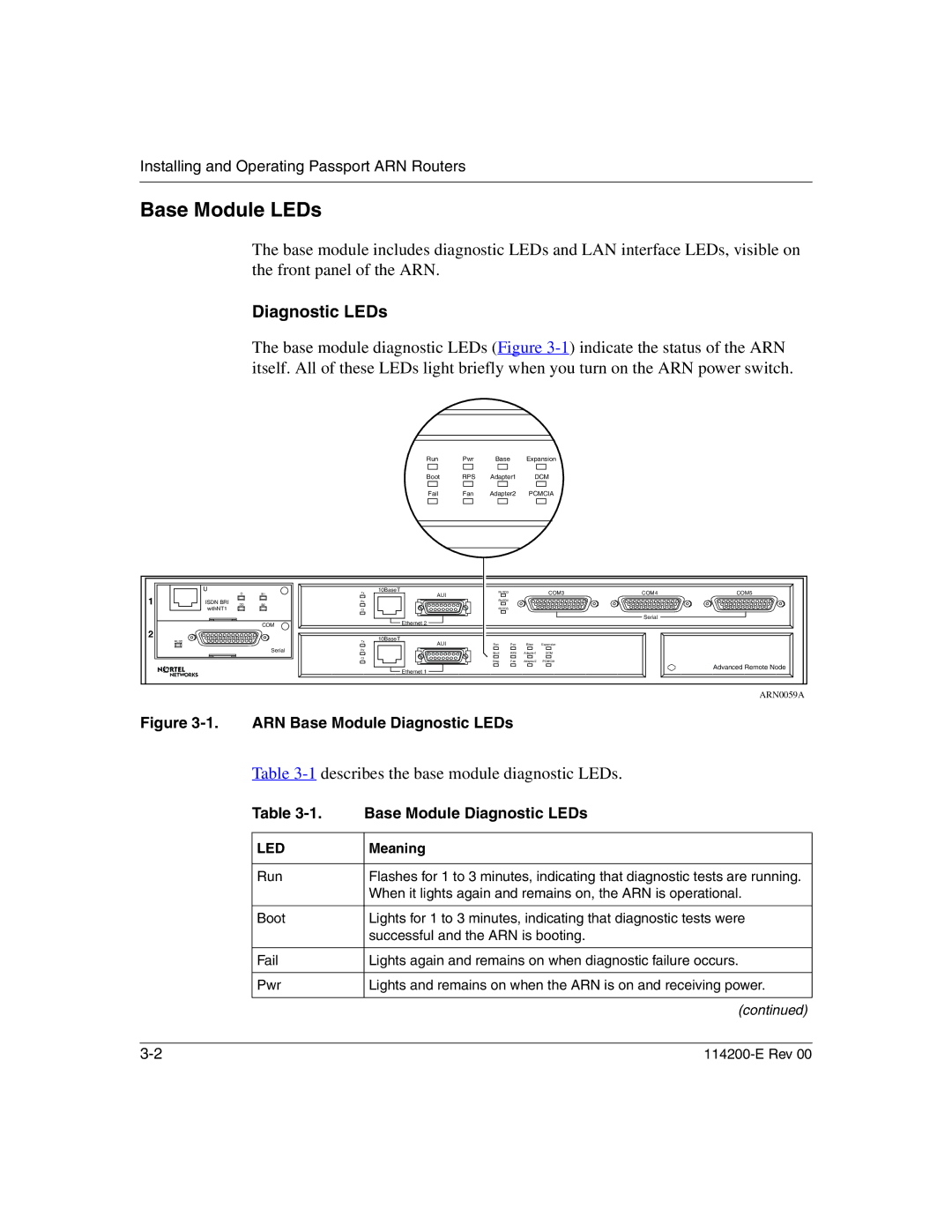
The base module includes diagnostic LEDs and LAN interface LEDs, visible on the front panel of the ARN.
Diagnostic LEDs
The base module diagnostic LEDs (Figure
Run Pwr Base Expansion
Boot RPS Adapter1 DCM
| Fail | Fan | Adapter2 | PCMCIA | |
|
|
|
|
|
|
|
|
|
|
|
|
|
|
|
|
|
|
| U | D | B1 | Tx | 10BaseT | RLSD3 |
|
| COM3 | COM4 | COM5 |
1 |
| AUI |
|
|
| ||||||
|
|
|
|
|
|
|
|
|
| ||
ISDN BRI | DD |
| Rx |
| RLSD4 |
|
|
|
|
| |
B2 |
|
|
|
|
|
|
|
| |||
| withNT1 |
|
| Cl |
| RLSD5 |
|
|
|
|
|
|
|
|
|
| Ethernet 2 |
|
|
|
| Serial |
|
|
|
| COM |
|
|
|
|
|
|
| |
2 |
|
|
|
| 10BaseT |
|
|
|
|
|
|
| RLSD |
|
| Tx | AUI | Run | Pwr | Base | Expansion |
|
|
|
|
|
|
|
|
| |||||
|
|
| Serial | Rx |
| Boot | RPS | Adapter1 | DCM |
|
|
|
|
|
| Cl |
| Diag | Fan | Adapter2 | PCMCIA |
|
|
|
|
|
|
|
|
|
| ||||
|
|
|
|
| Ethernet 1 |
|
|
|
|
| Advanced Remote Node |
|
|
|
|
|
|
|
|
|
|
| |
|
|
|
|
|
|
|
|
|
|
| ARN0059A |
Figure 3-1. ARN Base Module Diagnostic LEDs
Table 3-1 describes the base module diagnostic LEDs.
Table 3-1. Base Module Diagnostic LEDs
LED
Run
Boot
Fail
Pwr
Meaning
Flashes for 1 to 3 minutes, indicating that diagnostic tests are running. When it lights again and remains on, the ARN is operational.
Lights for 1 to 3 minutes, indicating that diagnostic tests were successful and the ARN is booting.
Lights again and remains on when diagnostic failure occurs.
Lights and remains on when the ARN is on and receiving power.
(continued)