Installing a WAN Adapter Module
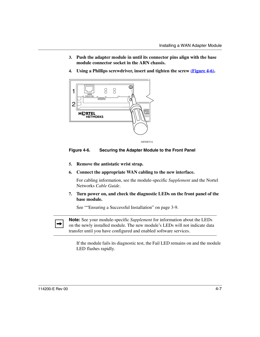
3.Push the adapter module in until its connector pins align with the base module connector socket in the ARN chassis.
4.Using a Phillips screwdriver, insert and tighten the screw (Figure
1 |
ISDN |
DSU/CSU |
2 |
ARN0033A
Figure 4-6. Securing the Adapter Module to the Front Panel
5.Remove the antistatic wrist strap.
6.Connect the appropriate WAN cabling to the new interface.
For cabling information, see the
7.Turn power on, and check the diagnostic LEDs on the front panel of the base module.
See ““Ensuring a Successful Installation” on page
Note: See your
If the module fails its diagnostic test, the Fail LED remains on and the module LED flashes rapidly.