1001rp server description | Standard 1.0 |
Rear panel diagram
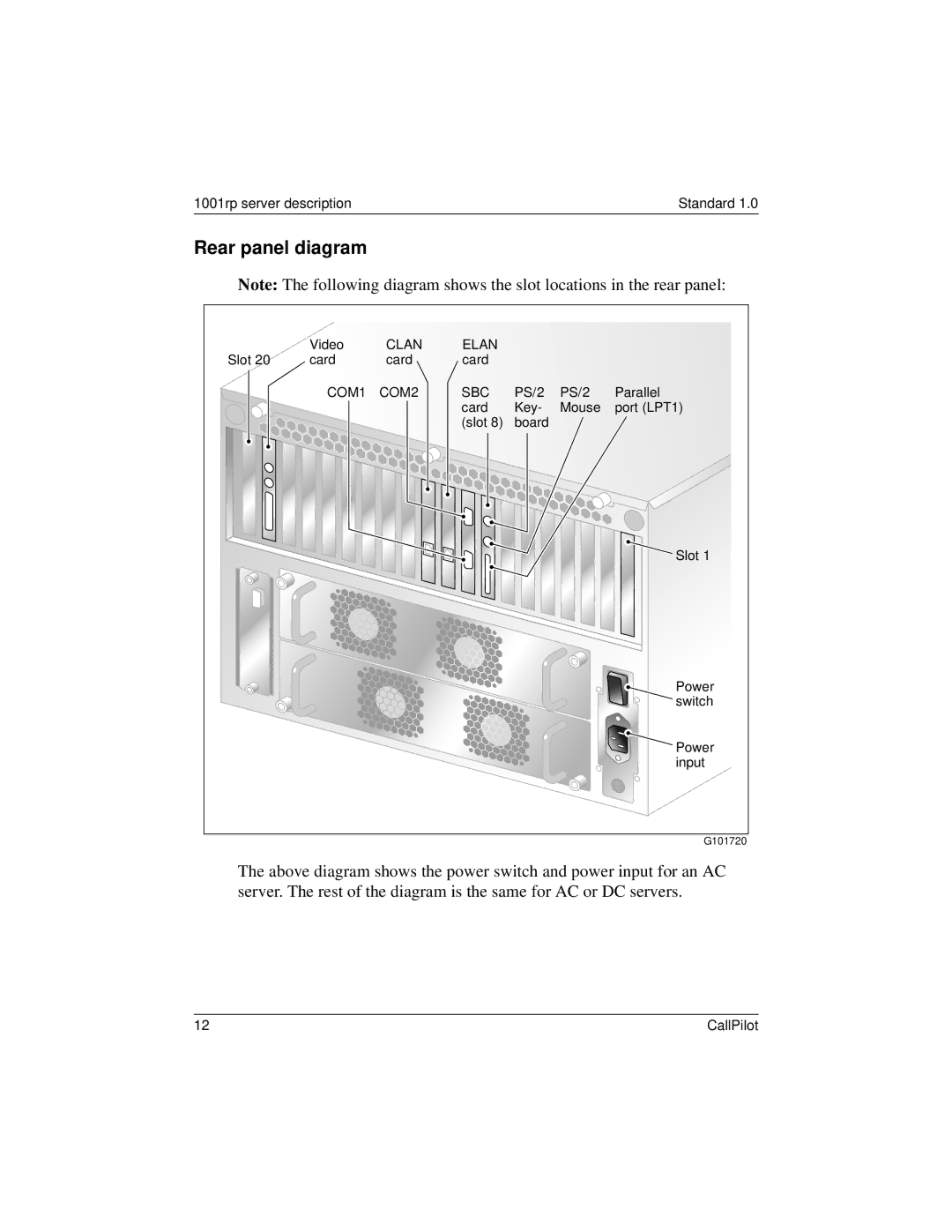
Note: The following diagram shows the slot locations in the rear panel:
| Video | CLAN | ELAN |
|
|
|
Slot 20 | card | card | card |
|
|
|
| COM1 | COM2 | SBC | PS/2 | PS/2 | Parallel |
|
|
| card | Key- | Mouse | port (LPT1) |
|
|
| (slot 8) | board |
|
|
|
|
|
|
|
| Slot 1 |
|
|
|
|
|
| Power |
|
|
|
|
|
| switch |
|
|
|
|
|
| Power |
|
|
|
|
|
| input |
|
|
|
|
|
| G101720 |
The above diagram shows the power switch and power input for an AC server. The rest of the diagram is the same for AC or DC servers.
12 | CallPilot |