Installing the server and connecting the peripheral devices | Standard 1.0 |
Modem DIP switches
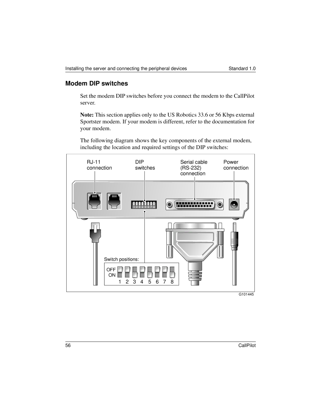
Set the modem DIP switches before you connect the modem to the CallPilot server.
Note: This section applies only to the US Robotics 33.6 or 56 Kbps external Sportster modem. If your modem is different, refer to the documentation for your modem.
The following diagram shows the key components of the external modem, including the location and required settings of the DIP switches:
|
| DIP |
|
|
|
|
| Serial cable | Power | |||
connection |
|
| switches |
|
| connection | ||||||
|
|
|
|
|
|
|
|
|
|
| connection |
|
|
| 1 | 2 | 3 | 4 | 5 | 6 | 7 | 8 |
|
|
|
Switch positions: |
|
|
|
|
|
|
|
|
| |||
OFF |
|
|
|
|
|
|
|
|
|
|
|
|
ON |
|
|
|
|
|
|
|
|
|
|
|
|
1 | 2 | 3 |
| 4 |
| 5 | 6 | 7 | 8 |
| ||
|
|
|
|
|
|
|
|
|
|
|
| G101445 |
56 | CallPilot |