PART 2 HARDWARE
2.1 Wall Mounting
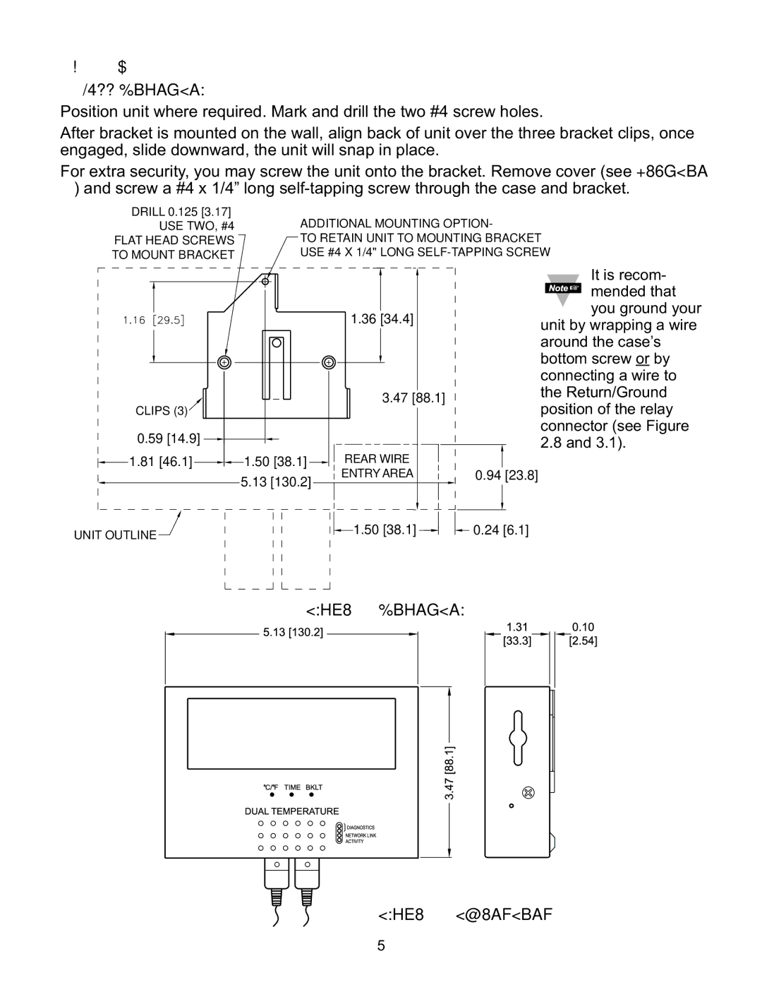
Position unit where required. Mark and drill the two #4 screw holes.
After bracket is mounted on the wall, align back of unit over the three bracket clips, once engaged, slide downward, the unit will snap in place.
For extra security, you may screw the unit onto the bracket. Remove cover (see Section 2.4) and screw a #4 x 1/4” long
DRILL 0.125 [3.17] |
|
|
|
USE TWO, #4 |
|
|
|
FLAT HEAD SCREWS |
|
|
|
TO MOUNT BRACKET |
|
|
|
|
| 1.36 [34.4] |
|
CLIPS (3) |
| 3.47 [88.1] |
|
|
|
| |
0.59 [14.9] | 1.50 [38.1] | REAR WIRE |
|
1.81 [46.1] | 0.94 [23.8] | ||
| 5.13 [130.2] | ENTRY AREA | |
UNIT OUTLINE |
| 1.50 [38.1] | 0.24 [6.1] |
It is recom- mended that you ground your
unit by wrapping a wire around the case’s bottom screw or by connecting a wire to the Return/Ground position of the relay connector (see Figure 2.8 and 3.1).
Figure 2.1 Mounting
Figure 2.2 Dimensions
5