4.3.6 Sensor Parameters (continued)
Below are some definitions of terms used in the Sensor Parameter pages. Sensor Name: a text field shown on the “Read Sensor” page.
TC Type: a list of thermocouple types to select from J, K, T, E, R, S, B, C, N, and L (J Din). (See Figure 12).
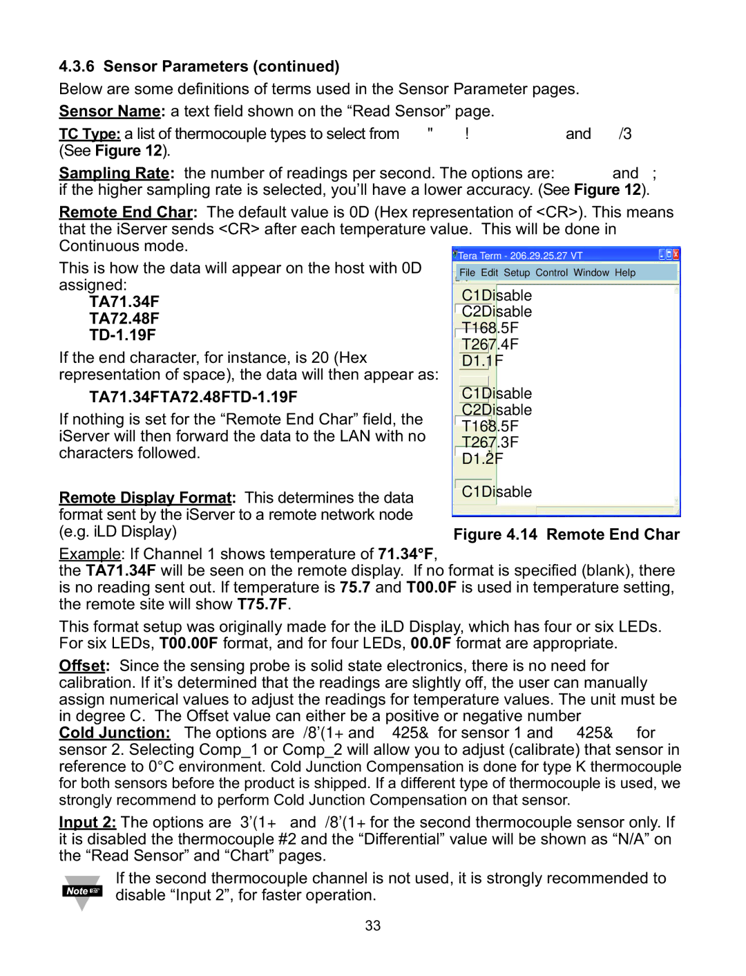
Sampling Rate: the number of readings per second. The options are: 2, 4, 8, and 12; if the higher sampling rate is selected, you’ll have a lower accuracy. (See Figure 12). Remote End Char: The default value is 0D (Hex representation of <CR>). This means that the iServer sends <CR> after each temperature value. This will be done in Continuous mode.
This is how the data will appear on the host with 0D assigned:
TA71.34F
TA72.48F
TD-1.19F
If the end character, for instance, is 20 (Hex representation of space), the data will then appear as:
TA71.34FTA72.48FTD-1.19F
If nothing is set for the “Remote End Char” field, the iServer will then forward the data to the LAN with no characters followed.
Remote Display Format: This determines the data format sent by the iServer to a remote network node (e.g. iLD Display)
Example: If Channel 1 shows temperature of 71.34°F,
the TA71.34F will be seen on the remote display. If no format is specified (blank), there is no reading sent out. If temperature is 75.7 and T00.0F is used in temperature setting, the remote site will show T75.7F.
This format setup was originally made for the iLD Display, which has four or six LEDs. For six LEDs, T00.00F format, and for four LEDs, 00.0F format are appropriate. Offset: Since the sensing probe is solid state electronics, there is no need for calibration. If it’s determined that the readings are slightly off, the user can manually assign numerical values to adjust the readings for temperature values. The unit must be in degree C. The Offset value can either be a positive or negative number
Cold Junction: The options are Disable and Comp_1 for sensor 1 and Comp_2 for sensor 2. Selecting Comp_1 or Comp_2 will allow you to adjust (calibrate) that sensor in reference to 0°C environment. Cold Junction Compensation is done for type K thermocouple for both sensors before the product is shipped. If a different type of thermocouple is used, we strongly recommend to perform Cold Junction Compensation on that sensor.
Input 2: The options are Enable and Disable for the second thermocouple sensor only. If it is disabled the thermocouple #2 and the “Differential” value will be shown as “N/A” on the “Read Sensor” and “Chart” pages.
If the second thermocouple channel is not used, it is strongly recommended to disable “Input 2”, for faster operation.
33